
Buffer-aware transmission rate control for real-time video streaming system

Active Publication Date: 2018-11-15
OMNIVISION TECH INC
View PDF13 Cites 27 Cited by
  • Summary
  • Abstract
  • Description
  • Claims
  • Application Information

AI Technical Summary

Benefits of technology

The patent text describes a video transmission system that adjusts the transmission rate based on the fill level of a buffer of the sender and reduces bandwidth consumption based on retransmission schemes. The system uses a combination of retransmission schemes and adjusts the transmission rate to achieve quality video using minimum bandwidth. This helps to overcome issues caused by bandwidth fluctuations, inadequate network bandwidth, and buffer underflow / overflow. The system can be used in real-time video communication systems, such as point-to-point systems, and can be implemented using applications that provide real-time video. The technical effects of the patent text include improved video quality, reduced bandwidth consumption, and improved efficiency of video transmission.

Problems solved by technology

Real-time video transmission over unreliable communication networks may incur various image quality problems, e.g., missing or distorted frames, freezing, stalls, interruptions, etc.
These issues may be caused by the bandwidth fluctuations, inadequate bandwidth, packet losses, and / or sender-side or receiver-side buffer underflow / overflow.
For example, if the instantaneous transmission rate of a sending device is larger than the available network bandwidth, many packets may arrive at the destination out of a deadline, which induces quality degradation.
Furthermore, in the case of long-distance transmissions, the bandwidth consumption may be increased, which results in unnecessary packet retransmissions.
Besides, the buffer underflow / overflow may result from abnormal transmission rates, and may affect the quality of the video.

Method used


Image

  • Buffer-aware transmission rate control for real-time video streaming system
  • Buffer-aware transmission rate control for real-time video streaming system
  • Buffer-aware transmission rate control for real-time video streaming system

Examples


Embodiment Construction

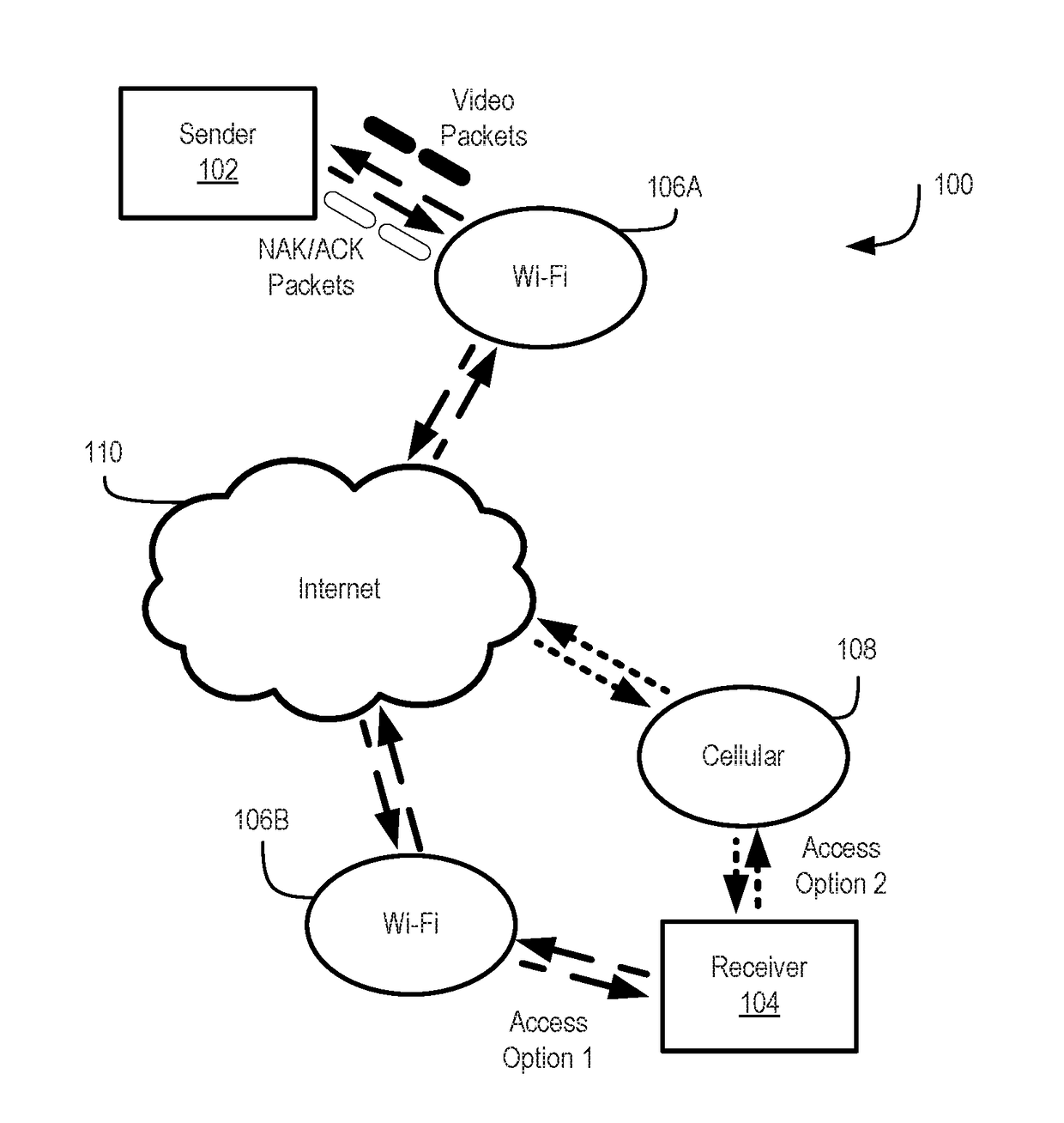
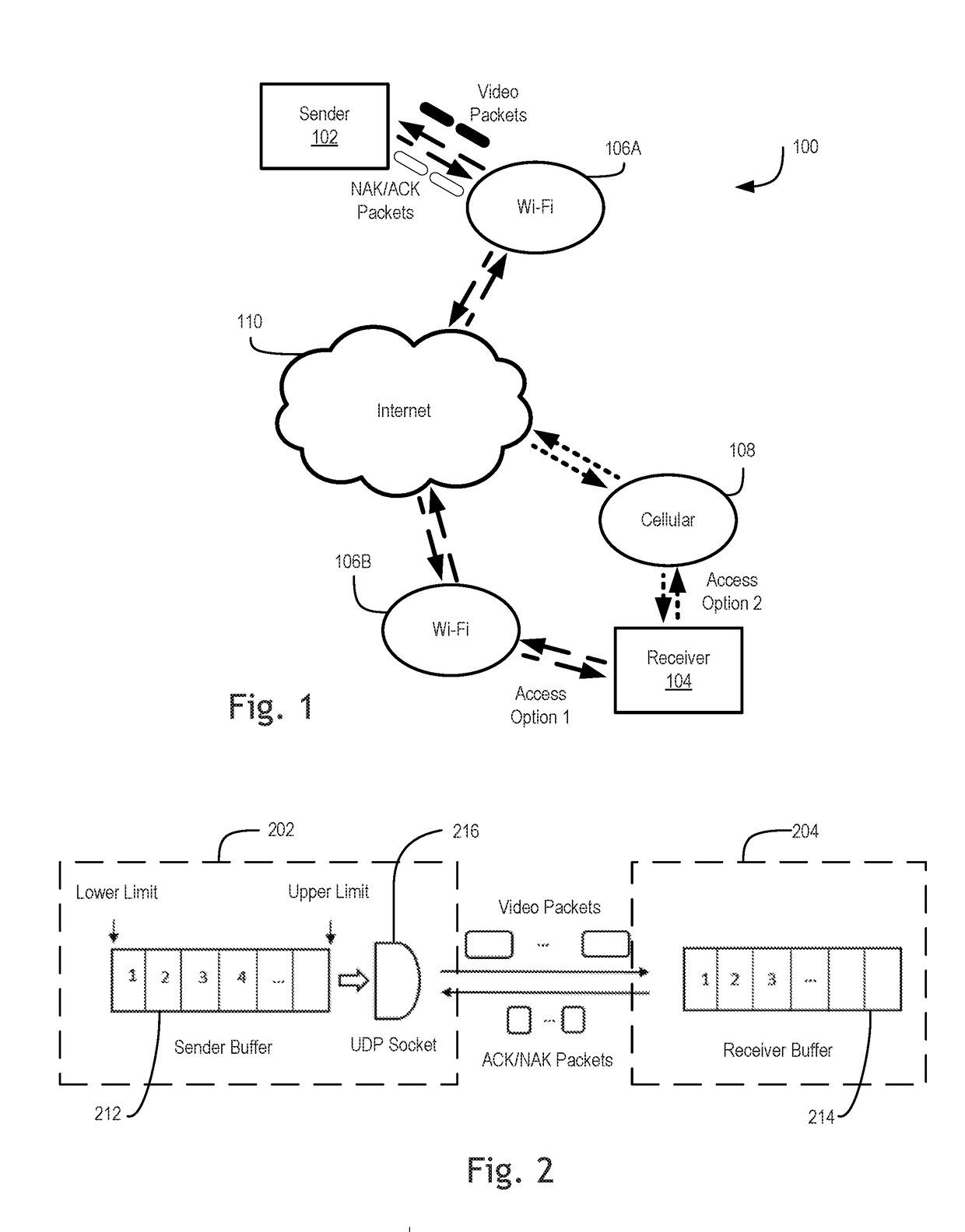
[0010]Examples of an apparatus and method for real-time video transmission system that adjusts a transmission rate based on a fill level of a sender-side buffer, and further reduces bandwidth consumption based on various retransmission schemes are described herein. In the following description, numerous specific details are set forth to provide a thorough understanding of the examples. One skilled in the relevant art will recognize; however, that the techniques described herein can be practiced without one or more of the specific details, or with other methods, components, materials, etc. In other instances, well-known structures, materials, or operations are not shown or described in detail to avoid obscuring certain aspects.

[0011]Reference throughout this specification to “one example” or “one embodiment” means that a particular feature, structure, or characteristic described in connection with the example is included in at least one example of the present invention. Thus, the app...


PUM


Abstract

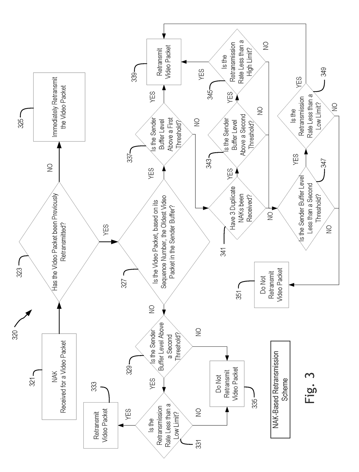
Systems and methods for buffer-aware transmission rate control for real-time video streaming are disclosed herein. An example method includes transmitting a first video packet at a transmission rate based on a buffer fill ratio of a buffer, where the transmission rate is adjusted in response to changes of the buffer fill ratio, selectively retransmitting a second video packet in response to a negative acknowledgement packet, where selectively retransmitting the second video packet is at least based on whether the second video packet has been previously retransmitted, a buffer level of the buffer, and a retransmission rate, and selectively retransmitting a third video packet in response to a non-receipt of an acknowledgement packet within a retransmission timeout, wherein selectively retransmitting the third video packet is at least based on whether the third video packet has been previously retransmitted, the buffer level of the buffer, and the retransmission rate.

Description

TECHNICAL FIELD[0001]This disclosure relates generally to video transmission systems, and in particular but not exclusively, relates to real-time video communication systems.BACKGROUND INFORMATION[0002]Real-time video transmission over unreliable communication networks may incur various image quality problems, e.g., missing or distorted frames, freezing, stalls, interruptions, etc. These issues may be caused by the bandwidth fluctuations, inadequate bandwidth, packet losses, and / or sender-side or receiver-side buffer underflow / overflow. For example, if the instantaneous transmission rate of a sending device is larger than the available network bandwidth, many packets may arrive at the destination out of a deadline, which induces quality degradation. Furthermore, in the case of long-distance transmissions, the bandwidth consumption may be increased, which results in unnecessary packet retransmissions. Besides, the buffer underflow / overflow may result from abnormal transmission rates,...

Claims


Application Information

Patent Timeline
IPC IPC(8): H04N21/44H04N21/647H04N21/6375H04L1/18
CPCH04N21/44004H04L1/1809H04N21/6375H04N21/64738H04N21/23406H04N21/26216H04N21/2662H04N21/4331H04N21/643H04L1/1825H04L1/1877H04L1/1883H04N21/43615H04N21/43637H04N21/6131H04N21/632
Inventor WU, JIYANWEN, ZHIZHUANWEI, JUNPAN, HUI
Owner OMNIVISION TECH INC
Learn More