Biomagnetic measurement method, biomagnetic measuring device, and biomagnetic measuring system
a biomagnetic measuring device and biomagnetic measuring technology, applied in the field of biomagnetic measurement method, biomagnetic measuring device, biomagnetic measuring system, can solve the problem of noise of interference magnetic-field signals
- Summary
- Abstract
- Description
- Claims
- Application Information
AI Technical Summary
Benefits of technology
Problems solved by technology
Method used
Image
Examples
first embodiment
[0023]A first embodiment of the present disclosure is described below with reference to the accompanying drawings.
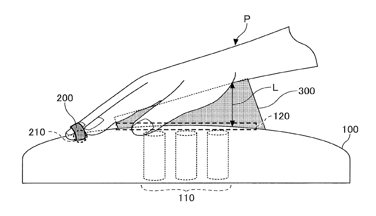
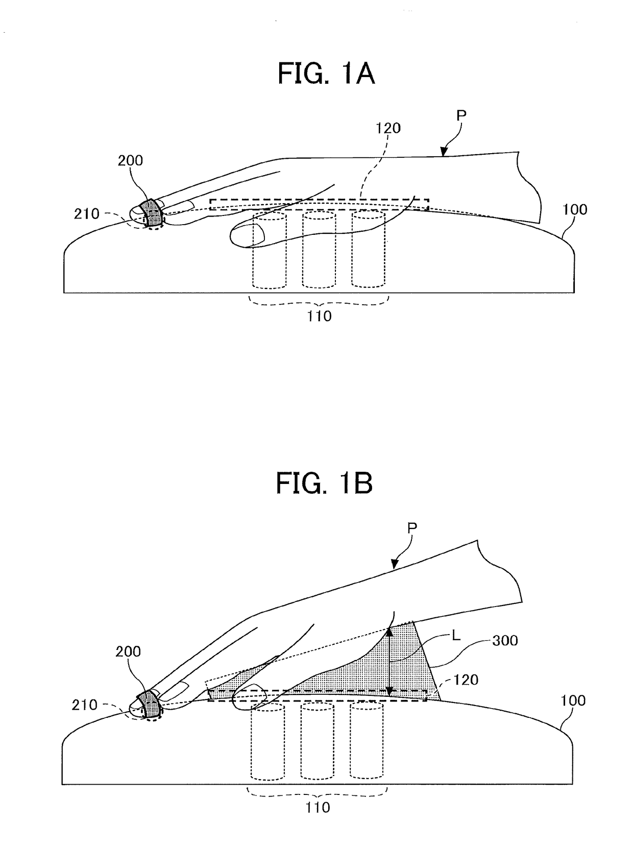
[0024]FIG. 1A and FIG. 1B are diagrams each illustrating biomagnetic measurement using a biomagnetic field measuring device 100 according to the first embodiment.
[0025]FIG. 1A is a diagram illustrating the first measurement to obtain the first measurement data, according to the present embodiment.
[0026]FIG. 1B is a diagram illustrating the second measurement to obtain the second measurement data, according to the present embodiment.
[0027]The biomagnetic field measuring device 100 according to the present embodiment is provided with a magnetic field detector 110, and measures the magnetic field caused by the electrical signals indicating the activities of the nerves at a to-be-measured site of a test object P, which are caused by a stimulus impressed by the nerve stimulator 200.
[0028]The nerve stimulator 200 according to the present embodiment may be, for example, a belt ...
second embodiment
[0128]A second embodiment of the present disclosure is described below with reference to the accompanying drawings. In the second embodiment, the processes that are performed by the analyzer 150 are different from those in the first embodiment. Accordingly, in the descriptions of the second embodiment as given below, only the differences from the first embodiment will be described. Like reference signs are given to like elements in the second embodiment, and their detailed description is omitted.
[0129]FIG. 12 is a flowchart of the processes that are performed by the analyzer 150 of the biomagnetic field measuring device 100, according to the second embodiment.
[0130]The processes in steps S1201 to S1202 in FIG. 12 are equivalent to the processes in the steps 5501 and 5502 in FIG. 5, and thus their detailed description is omitted.
[0131]Once the analyzer 150 obtains the first measurement data and the second measurement data, the analyzer 150 makes the signal levels of the first measure...
third embodiment
[0134]A third embodiment of the present disclosure is described below with reference to the accompanying drawings. In the third embodiment, the functions of the analyzer 150 are provided for an external device outside the biomagnetic field measuring device. In this respect, the third embodiment is different from the first embodiment. Accordingly, in the descriptions of the third embodiment as given below, like reference signs used in the first embodiment are given to like elements in the third embodiment, and their detailed description is omitted.
[0135]FIG. 13 is a diagram illustrating a biomagnetic field measuring device according to the third embodiment.
[0136]A biomagnetic field measuring device 100A according to the present embodiment makes up a biomagnetic field measuring system 500 together with an information processing device 400. In the biomagnetic field measuring system 500 according to the present embodiment, the biomagnetic field measuring device 100A and the information ...
PUM
 Abstract
Description
Claims
Application Information
 - R&D
- Intellectual Property
- Life Sciences
- Materials
- Tech Scout
- Unparalleled Data Quality
- Higher Quality Content
- 60% Fewer Hallucinations
Browse by: Latest US Patents, China's latest patents, Technical Efficacy Thesaurus, Application Domain, Technology Topic, Popular Technical Reports.
© 2025 PatSnap. All rights reserved.Legal|Privacy policy|Modern Slavery Act Transparency Statement|Sitemap|About US| Contact US: help@patsnap.com


