Two-Way Output Reverse-Torque Clutch

Inactive Publication Date: 2018-11-22
HALL LABS LLC
View PDF5 Cites 3 Cited by
  • Summary
  • Abstract
  • Description
  • Claims
  • Application Information

AI Technical Summary

Benefits of technology

The patent describes a two-way output reverse-torque clutch that can be used with a single pin. The clutch has a torque input with a segmented race, one or more pins that can be removed, and a torque output that rotates within the segmented race. The torque output has a hard material surface that presses against the pins, preventing torque from being transmitted to the input when there is a direct torque on the output. The clutch can prevent torque from being transmitted from the input to the output with just one pin. This design solves issues with previous clutches and ensures smooth operation.

Problems solved by technology

One such challenge is making devices more compact, while still retaining robust functionality.
An example of such a device may be found in U.S. Patent Publication Number 2015 / 0284221 to David Hall et al. entitled “Compact Motorized Lifting Device.” In general, a problem with motorized devices that wind / roll-up components is preventing reverse-torque from unwinding / unrolling the components.
However, such devices may be complex.

Method used


Image

  • Two-Way Output Reverse-Torque Clutch
  • Two-Way Output Reverse-Torque Clutch
  • Two-Way Output Reverse-Torque Clutch

Examples


Embodiment Construction

[0017]A detailed description of embodiments of an apparatus is provided below by example, with reference to embodiments in the appended figures. Those of skill in the art will recognize that the features of the apparatus as described by example in the figures below could be arranged and designed in a variety of different configurations without departing from the scope of the claims. Thus, the detailed description below and the depictions of embodiments in the figures is representative of the claimed invention, and is not intended to limit the scope of the claims.

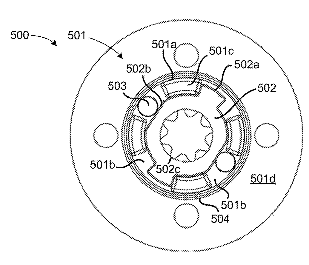
[0018]Embodiments of a two-way output reverse-torque clutch are described herein. The clutch may include a torque input, a pin, a torque output, and an outer race. The clutch may be two-way output and reverse-torque operable with as few as one pin. The torque input may include a segmented race. The pin may be removably disposed adjacent to, and between, at least two segmented race segments. The torque output may be rotatably...


PUM


Abstract

Embodiments of a two-way output reverse-torque clutch described herein may include a torque input having a segmented race, a pin removably disposed adjacent to, and between, at least two segmented race segments, a torque output rotatably disposed within the segmented race, and an outer race encircling the segmented race. The torque output may include a cam surface with an interference point corresponding to at least one of the one or more pins. The cam surface may have an interference point. The outer race may be in slideable contact with the segmented race. A torque exerted directly on the output may force the interference point against the pin, wedging the pin between the interference point and the outer race and preventing torque from being transmitted to the input from the output. The clutch may prevent torque from being transmitted to the torque input from the torque output with one pin.

Description

TECHNICAL FIELD[0001]This invention relates generally to smart devices and more specifically to roll-up and / or winding devices.BACKGROUND[0002]With the proliferation of the Internet of Things, and more specifically of smart home and / or remotely-controlled devices, consumers and manufacturers are facing new challenges. One such challenge is making devices more compact, while still retaining robust functionality. An example of such a device may be found in U.S. Patent Publication Number 2015 / 0284221 to David Hall et al. entitled “Compact Motorized Lifting Device.” In general, a problem with motorized devices that wind / roll-up components is preventing reverse-torque from unwinding / unrolling the components. Some reverse clutches have been designed that prevent reverse-torque. However, such devices may be complex. Reducing complexity, such as by reducing the number of required parts, may help in streamlining manufacturing processes and simplifying maintenance. Thus, there is room for imp...

Claims


Application Information

Patent Timeline
IPC IPC(8): F16D43/20F16D7/00
CPCF16D7/00F16D43/20E06B9/72F16D43/2028E06B2009/725
Inventor HALL, DAVID R.MILES, JEROMEPRIDDIS, ANDREWMADSEN, DANIELTAYLOR, BENJAMINPRIDDIS, JACKSONKNIGHT, JEDEDIAHFOX, JOE
Owner HALL LABS LLC
Why Eureka
Try Eureka