
Internal structure for an electrical heating device with heating element freely coiled at least in sections and electrical heating device

a technology of electrical heating devices and internal structures, which is applied in the direction of ohmic resistance heating, electrical heating, electrical apparatus, etc., can solve the problems of large spatial requirements, large degree of freedom of spatial arrangement of electrical heating elements, and limit the resistance per unit of length that can be achieved, so as to achieve direct and targeted heat dissipation to the environment

Active Publication Date: 2018-12-06
TUERK & HILLINGER
View PDF6 Cites 0 Cited by
  • Summary
  • Abstract
  • Description
  • Claims
  • Application Information

AI Technical Summary

Benefits of technology

The invention provides an internal structure for an electrical heating device that allows for the installation of heating elements in a flexible way. The elements can be coiled and inserted into a metal sheathing, which can also contain insulating powder or granulate. This allows for the creation of a compact, efficient electrical heating device that can be easily installed.

Problems solved by technology

However, this solution loses a considerable amount in terms of degrees of freedom for the spatial arrangement of the electrical heating element.
Naturally, however, this arrangement is associated with a certain minimum cross-section of the electrical heating conductor, which limits the resistance per unit of length that can be achieved.
As a result, however, this produces relatively large spatial requirements for the electrical heating element, so it cannot be used in all cases.

Method used


Image

  • Internal structure for an electrical heating device with heating element freely coiled at least in sections and electrical heating device
  • Internal structure for an electrical heating device with heating element freely coiled at least in sections and electrical heating device
  • Internal structure for an electrical heating device with heating element freely coiled at least in sections and electrical heating device

Examples


Embodiment Construction

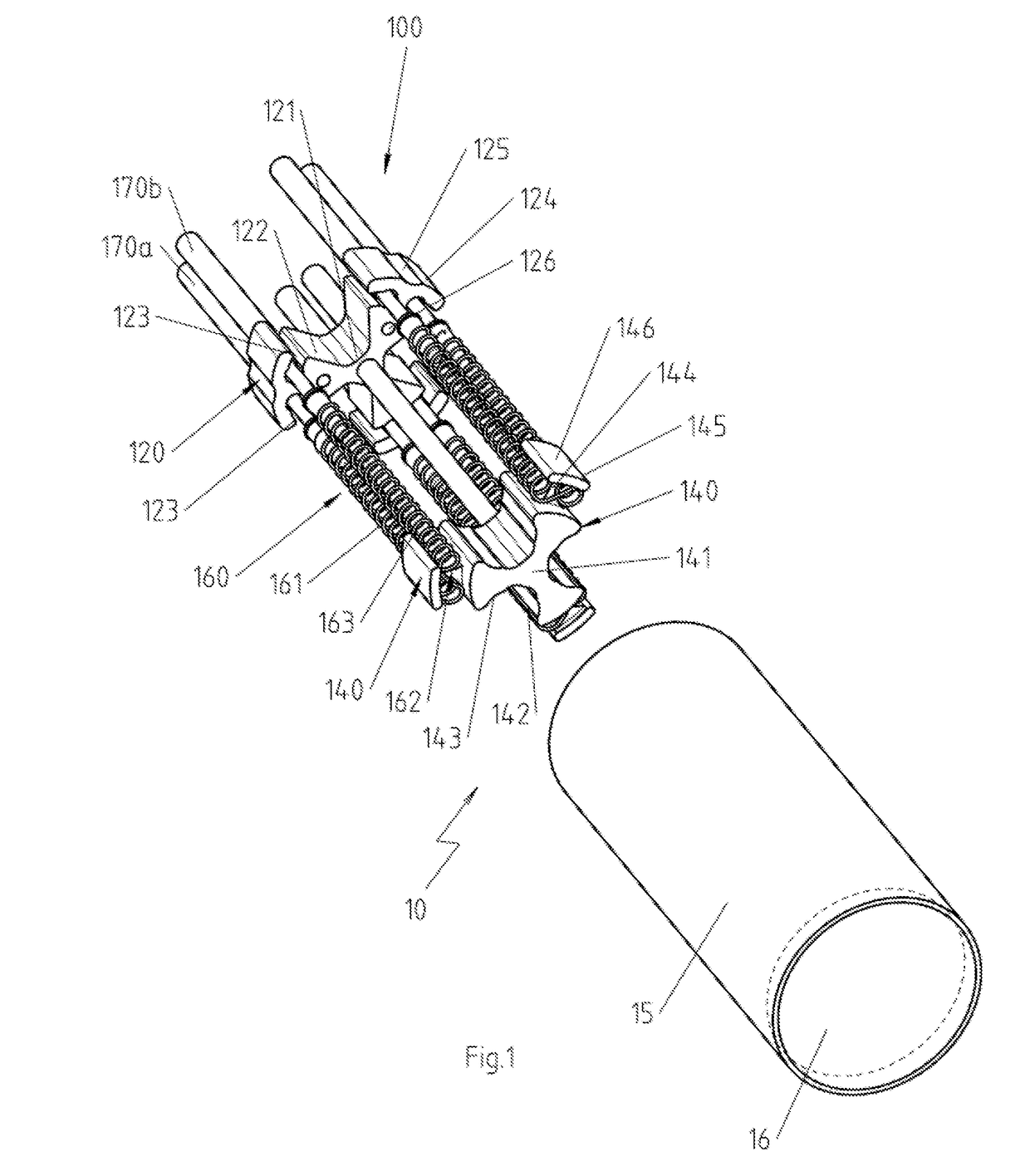
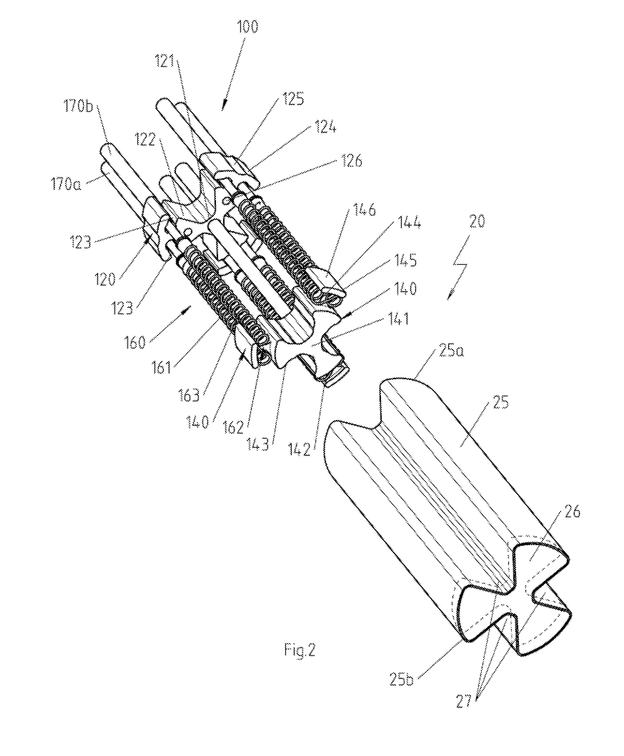
[0035]FIG. 1 shows an electrical heating device 10 in a partial exploded-view illustration, in which are visible the tubular metal sheathing 15, which is a cylindrical sheathing with base 16 in the shown embodiment and the internal structure 100 for the electrical heating device 10, which is actually arranged in a powdery material that is electrically insulating but has good thermal conductivity properties, such as, e.g., magnesium oxide embedded within the tubular metal sheathing 15.

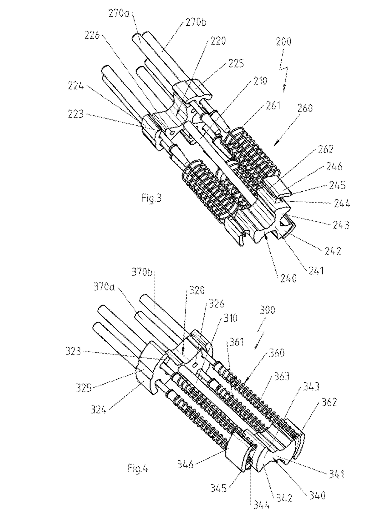
[0036]The internal structure 100 has a connection section 120, a turnaround section 140 and a spacer 110 that runs between the connection section 120 and the turnaround section 140. The profile of the here rod-shaped spacer 110 or its center axis between the connection section 120 and turnaround section 140 defines a direction relative to which both the connection section 120 and also the turnaround section 140 top the spacer 110 in the radial direction, wherein the measure of this topping varies as a f...


PUM


Abstract

An internal structure for an electrical heating device includes an electrical heating element. The internal structure includes a connection section for holding an end section of the electrical heating element or a connecting wire, with which one of the two end sections is connected. A turnaround section is positioned opposite the connection section. A spacer runs between the connection section and the turnaround section and is topped by the turnaround section in a radial direction relative to the profile of the spacer. The turnaround section has, for a turned-around electrical heating element or for a turned-around connecting wire in the area topping the spacer, a connecting bar by means of which the electrical heating element or the connecting wire is guided and thus turned around, with this connecting wire being connected to an end section.

Description

CROSS-REFERENCE TO RELATED APPLICATIONS[0001]This application claims priority under 35 U.S.C. § 119(b) to German Patent Application No. 20 2017 103 387, filed Jun. 6, 2017, the disclosure of which is incorporated herein by reference in its entirety.BACKGROUND OF THE INVENTION[0002]Many electrical heating devices have tubular metal sheathings, in whose interior an electrical heating element is arranged, which is typically fixed in its position after its arrangement in the interior of the tubular metal sheathing by the interspersing and optional compacting of a powder or granulate that has, in particular, electrically insulating properties, and insulated electrically from the tubular metal sheathing if the electrical heating element itself is already not electrically insulated on its outer side.[0003]The manufacture of such electrical heating devices is then particularly simple if the electrical heating element is provided as a separate assembly, which is preconfigured, in particular,...

Claims


Application Information

Patent Timeline
Patent Type & Authority Applications(United States)
IPC IPC(8): H05B3/44
CPCH05B3/44H05B2203/002H05B3/02H05B3/40H05B3/06H05B3/16H05B3/46
Inventor SCHLIPF, ANDREAS
Owner TUERK & HILLINGER
Learn More