
LED (light-emitting diode) lamp bead

A technology of LED lamp beads and lamp beads, which is applied in lighting devices, cooling/heating devices of lighting devices, light sources, etc., can solve the problems of waste of materials, waste of electricity, temperature rise, etc., to reduce use costs, reduce production costs, The effect of prolonging the service life

Inactive Publication Date: 2014-03-26
陈广友
View PDF6 Cites 0 Cited by
  • Summary
  • Abstract
  • Description
  • Claims
  • Application Information

AI Technical Summary

Problems solved by technology

[0002] At present, the existing LED lighting lamps in the domestic and foreign markets have an integrated structure of lamp beads, power supply and lamp housing. Because the lamp beads of existing LED lamps are welded to the positive and negative ends of the lamp beads on the aluminum substrate. On the front side, the aluminum substrate is welded to the power wire. When installing the LED lamp, the reverse side of the aluminum substrate is in contact with the inner plate of the lamp holder (lamp housing) by coating a heat-conducting paste such as silicone grease. LED) or a small component is damaged, the whole LED lamp can not be used, and all are scrapped, but the cost of the aluminum substrate accounts for a considerable proportion of the entire LED lamp, resulting in a great waste of materials, resulting in the price of the LED lamp. At the same time, because the efficiency of LED lamps is easily affected by high temperature and drops sharply, more heat is generated in addition to wasting electricity, causing the temperature to rise further, which is easy to form a vicious circle. In addition to wasting electricity, it will also shorten the life of LEDs. Therefore, good heat dissipation also has a great impetus for the popularization and application of LED lamps. However, the existing LED lamp beads use aluminum substrates as electrical substrates and the effect of heat dissipation through coated thermal paste is not ideal.

Method used


Image

  • LED (light-emitting diode) lamp bead
  • LED (light-emitting diode) lamp bead
  • LED (light-emitting diode) lamp bead

Examples


Embodiment Construction

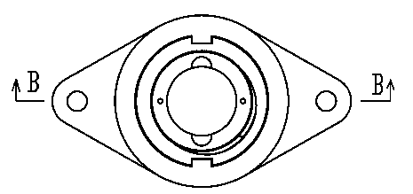
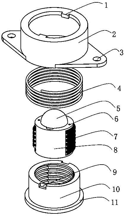
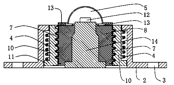
[0020] Such as Figure 1-6 As shown, the LED lamp bead of the present invention includes a lamp bead and a lamp bead holder for installing the lamp bead, wherein the lamp bead includes a light-emitting chip 12, a silica gel lens 5, a cylindrical insulating plastic 8 and positive and negative electrode welding pieces 13, and the light-emitting chip 12 is provided with a chip heat dissipation base 14, the positive and negative soldering pieces 13 are connected to the light-emitting chip 12 through conductive wires, and the outer circumference of the cylindrical insulating plastic 8 is covered with positive and negative guide plates 7 with external threads 15. The negative electrode guide plate 7 is connected with the positive and negative electrode welding pieces 13 respectively; the lamp bead holder includes the lamp bead holder inner shell 10 and the lamp bead holder outer shell 2, and the inner surface of the lamp bead holder inner shell 10 is covered with positive and negativ...


PUM


Abstract

The invention discloses an LED (light-emitting diode) lamp bead which comprises a lamp bead body and a lamp bead base, wherein the lamp bead body comprises a luminous chip, cylindrical insulation plastics, a positive pole welding piece and a negative pole welding piece, wherein the inner surface of an inner shell of the lamp bead base is covered with a positive pole contact plate and a negative pole contact plate which are provided with internal thread; a positive pole guide plate and a negative pole guide plate which are provided with external threads are covered at the periphery of the cylindrical insulation plastics; the positive pole guide plate and the negative pole guide plate are respectively connected with the positive pole welding piece and the negative pole welding piece; and the lamp bead body is connected with the lamp bead base by virtue of the internal threads and the external threads. According to the invention, the single body structure of the traditional LED lamp bead is completely changed, the lamp bead body and the lamp bead base of the LED lamp bead are designed into a detachable structure, and the lamp bead body and the lamp bead base can be separated from each other in a way of rotary disassembly, so that the LED lamp bead is convenient to replace; a lamp bead chip heat dissipation base stably clings to a lamp shell cooling plate by a stabilizing spring on the lamp bead base, so that the heat dissipation effect is good, and the service life of the LED lamp bead is prolonged; and an aluminium base plate is not used, so that the raw material is saved, and the production cost of the LED lamp is lowered.

Description

Technical field [0001] The invention involves a new type of LED lamp bead. Background technique [0002] At present, the existing LED lighting on the domestic and foreign markets, its lamp beads and power supply to the lamp shell are a whole structure. Since the existing LED lamps are the positive and negative extreme welding of the lamp beads on the aluminum substrate,On the front, the aluminum substrate welded power wire. When installing the LED lamp, the opposite side of the aluminum substrate is in contact with the inside of the lamp (lamp shell) in the lamp (lamp shell) in the back of the aluminum substrate.LED) or a small component is damaged, the overall LED light cannot be used, all scrapped, and the cost of aluminum substrates accounts for a considerable proportion in the entire LED light, resulting in a great waste of materials, resulting in the price of LED lights always alwaysAt the same time, because the efficiency of LED lights is easily affected by high temperature...

Claims


Application Information

Patent Timeline
Patent Type & Authority Patents(China)
IPC IPC(8): F21S2/00F21V19/00F21V29/00F21Y101/02F21K9/235F21V29/70F21Y115/10
Inventor 陈广友
Owner 陈广友
Learn More