

Air cooling device for side face of computer case
An air-cooling device and computer technology, applied in the computer field, can solve the problems such as the inability to transfer heat quickly, the heat transmission path is long, and the service life is not long, so as to achieve the effects of convenient maintenance, reducing dust volume and prolonging service life.
- Summary
- Abstract
- Description
- Claims
- Application Information
AI Technical Summary
Problems solved by technology
Method used
Image

Examples
Embodiment
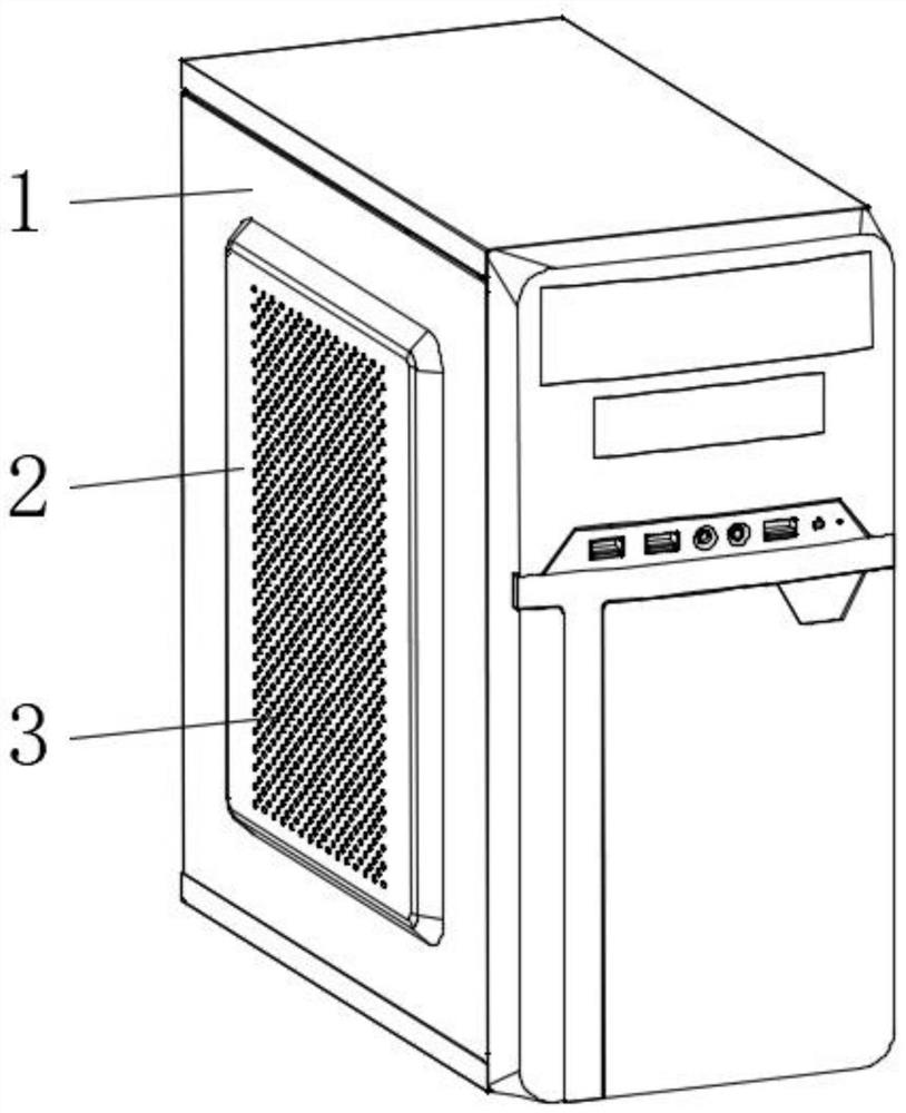
[0071] An embodiment of the present invention provides an air cooling device for the side of a computer case, such as Figure 1-7 shown, including:
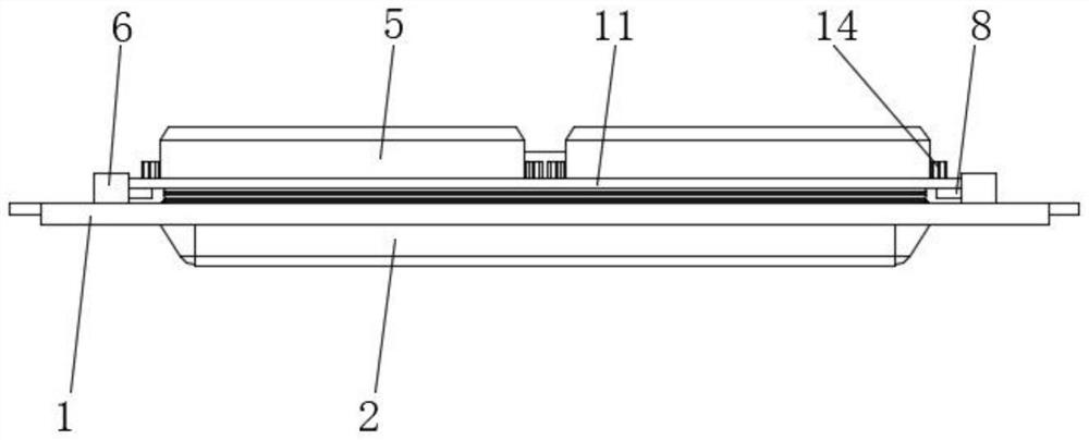
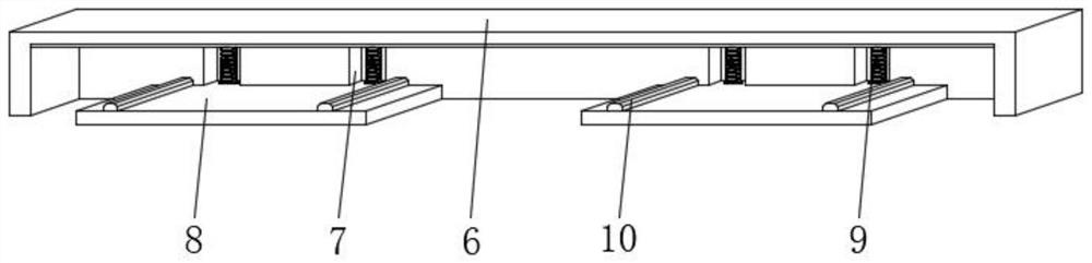
[0072] The case side plate 1 installed on the side of the computer case, the middle position of the case side plate 1 is provided with an outwardly protruding heat dissipation plate 2, several groups of heat dissipation holes 3 are opened on the heat dissipation plate 2, and the rear end surface of the heat dissipation plate 2 is provided with a mounting Groove 4, the interior of the installation groove 4 is provided with a shielding assembly for shielding the cooling holes 3, and the side plate 1 of the chassis is provided with a fixing assembly; and
[0073] The air-cooled assembly, the air-cooled assembly includes an installation assembly and several groups of cooling fans 5, the installation assembly is installed on the fixed assembly, and the cooling fans 5 are movably installed on the installation assembly.
[0074] furthe...
PUM
 Abstract
Description
Claims
Application Information