
Injection apparatus comprising a laterally attached actuation member for triggering the product release

a technology of actuation member and product release, which is applied in the direction of intravenous devices, medical syringes, infusion syringes, etc., to achieve the effect of easy manufacturing and high user comfor

Active Publication Date: 2018-12-20
YPSOMED AG
View PDF4 Cites 2 Cited by
  • Summary
  • Abstract
  • Description
  • Claims
  • Application Information

AI Technical Summary

Benefits of technology

The technical effect of this patent text is to provide an injection apparatus with a drive and metering system that offers high user comfort and is easy to produce.

Problems solved by technology

It is a problem to make available a drive and metering apparatus for an injection apparatus, where the drive and metering apparatus should afford high user comfort and be easy to manufacture.

Method used


Image

  • Injection apparatus comprising a laterally attached actuation member for triggering the product release
  • Injection apparatus comprising a laterally attached actuation member for triggering the product release
  • Injection apparatus comprising a laterally attached actuation member for triggering the product release

Examples


first embodiment

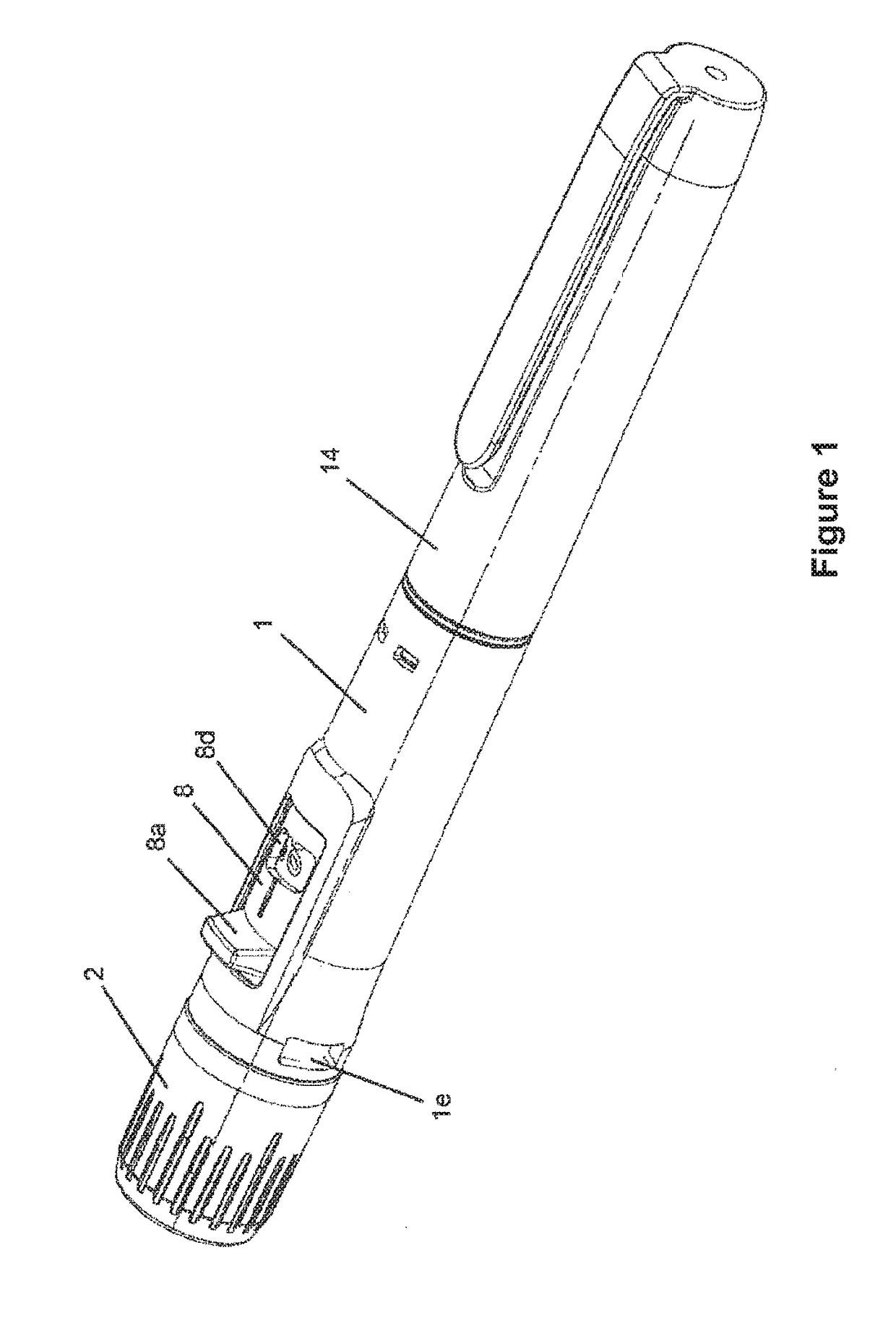
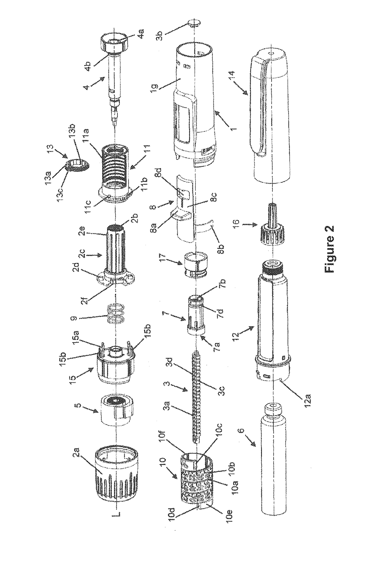
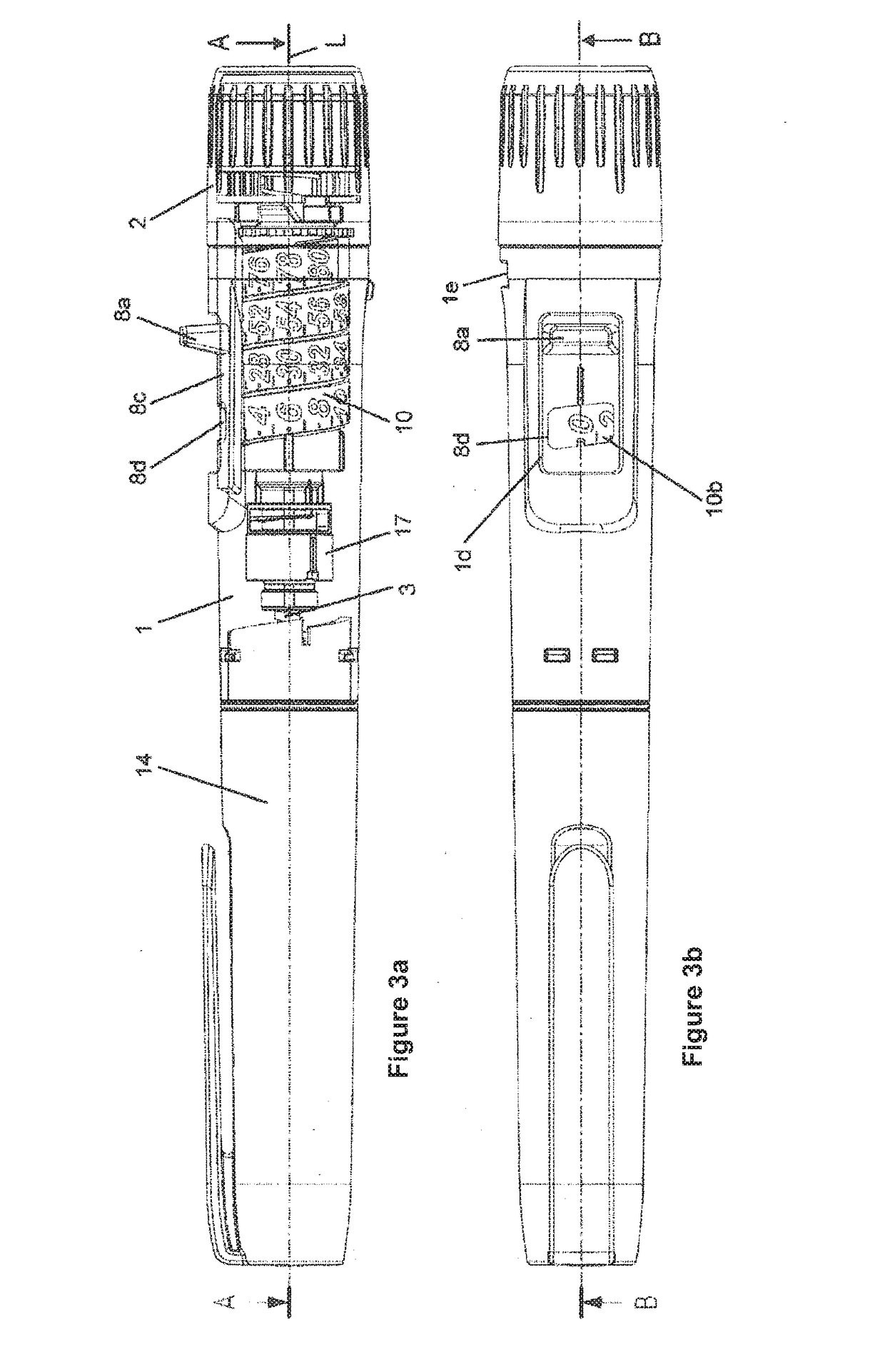
[0086]The drive and metering apparatus of the first embodiment in FIGS. 1 to 6d has a sleeve-shaped housing 1, which comprises an outer sleeve 1g and an inner sleeve 1h which is connected and concentrically disposed thereto. The inner sleeve 1h is connected, in particular snapped together, with the outer sleeve 1g non-rotatably and axially fixed. Alternatively, the outer sleeve 1g could be made in one part with the inner sleeve 1h. The inner sleeve 1h and the outer sleeve 1g are firmly connected via a ring-shaped ridge formed by the inner sleeve 1h. The housing 1, in particular the inner sleeve 1h, has an internal thread 1a, which engages in an external thread 3c of a threaded rod 3a of a driven member 3, so that the threaded rod 3a and thus the driven member 3 can be screwed in the distal direction relative to the housing 1 and along a lengthwise axis L. The driven member 3 comprises the threaded rod 3a and a plate-shaped flange 3b which is affixed to the distal end of the threaded...

second embodiment

[0116]an injection apparatus with the drive and metering apparatus according to the invention, which is shown in FIGS. 7 to 11b, comprises an elongated housing 101. A product container holder 112, in which a product container 106, in this example a cartridge, is accommodated, is disposed at the front or distal end of the housing 101. A needle unit 116 is disposed at the distal end of the cartridge 106 or the product holder container 112 where the preferably liquid product or medicament contained in the product container 106 can be discharged through the needle of the needle unit 116.

[0117]The product container holder 112 and optionally the needle unit 116 are covered by a removable cap 114, which is separably attached at the product container holder 112, in particular is snapped on. The drive and metering apparatus forms, for example with the product holder 106 and product holder container 112 mounted on the drive and metering apparatus, an injection apparatus.

[0118]The housing 101 ...


PUM


Abstract

A drive and metering apparatus for an injection apparatus for releasing a liquid product, the drive and metering apparatus comprising: a) a housing, b) a dose adjustment member, which is rotatable relative to the housing for adjusting the product dose to be released, c) an actuation member which is displaceable from a non-actuated position, which it assumes while adjusting the product dose to be released, into an actuated position, which it assumes while it releases the product, wherein the displacement of the actuation member into the actuated position triggers a product release and the actuation member comprises an actuation section, which is accessible to a user of the drive and metering apparatus and by means of which the user can displace the actuation member from the non-actuated position into the actuated position, d) wherein the actuation section is arranged distally in relation to the dose adjustment member.

Description

CROSS-REFERENCE TO RELATED APPLICATIONS[0001]This application is a continuation of International Application No. PCT / CH2017 / 000010 filed Feb. 2, 2017, which claims priority to Swiss Application No. 00236 / 16 filed Feb. 23, 2016, the entire contents of all of which are incorporated by reference herein in their entirety.BACKGROUND[0002]The invention concerns an injection apparatus for administration of a liquid product, especially a medicament, for example insulin for treatment of diabetes. In detail, the invention concerns a drive and metering apparatus for such an injection apparatus. The drive and metering apparatus comprises an actuation member having an actuation section, which is mounted laterally on the elongated drive and metering apparatus or injection apparatus and which does not form the rear end of the apparatus.[0003]The term “medicament” here comprises any flowable medicinal formulation that is suitable for controlled administration through a means, for example a cannula ...

Claims


Application Information

Patent Timeline
Patent Type & Authority Applications(United States)
IPC IPC(8): A61M5/315
CPCA61M5/31528A61M5/31573A61M5/31556A61M2005/3126A61M5/31553A61M5/3158A61M5/3213
Inventor STREIT, URSINASCHENKER, SUSANNEHIRSCHEL, JURG
Owner YPSOMED AG
Learn More