Processing method

Inactive Publication Date: 2018-12-20
ROLLS ROYCE PLC
View PDF0 Cites 1 Cited by
  • Summary
  • Abstract
  • Description
  • Claims
  • Application Information

AI Technical Summary

Benefits of technology

[0035]In some embodiments, the processing method further comprises subjecting the component to an aging step for an aging tim

Problems solved by technology

The resulting component often comprises defects such as cracks, porosity, voids and layering defects.
One problem with the known prior art methods is that hot isostatic pressing requires high temperature and high pressure and thus is a costly process.
As such, its availability is limited to only a few suppliers.
Also

Method used


Image

  • Processing method
  • Processing method
  • Processing method

Examples


Embodiment Construction

[0054]A turbine or compressor component such as a blade or stator for use in a gas turbine aero-engine is manufactured using an ALM method in which a layer of powdered CM247LC having a particle size of between 15 and 60 microns is deposited on a base plate and fused into a 2D first fused layer using a scanning laser beam to melt and fuse the powdered CM247LC. Next a second layer of powdered CM247LC is deposited on the first fused layer and fused into a 2D second fused layer using the scanning laser beam, the second fused layer being fused to the first fused layer.

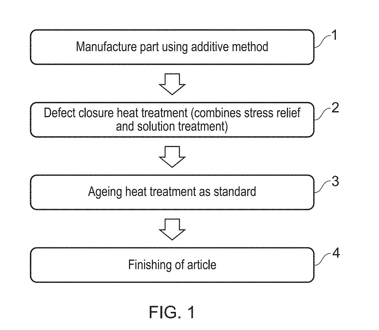
[0055]The deposition and fusing of powdered CM247LC is repeated until the desired 3D component is formed from the 2D layers. This is step 1 shown in FIG. 1

[0056]The component is first processed using a surface finishing step which is applied to reduce the extent of surface asperities which arise as a result of semi-fused powdered CM247LC. The surface finishing step also acts to clean the component of loose powdered CM247LC....


PUM

PropertyMeasurementUnit
Temperatureaaaaaaaaaa
Timeaaaaaaaaaa
Particle sizeaaaaaaaaaa

Abstract

The present disclosure relates to a method for processing a component formed by an ALM method using a γ′-strengthened superalloy having a γ′ solvus temperature. The processing method comprises heating the component to a treatment temperature at or above the γ′ solvus temperature at a rate equal to or greater than 50 ° C./min and then cooling the component at a rate of greater than 60° C./min.

Description

CROSS-REFERENCE TO RELATED APPLICATIONS[0001]This application is based upon and claims the benefit of priority from British Patent Application No. GB 1709540.7, filed on 15th Jun. 2017, the entire contents of which are herein incorporated by reference.BACKGROUNDTechnical Field[0002]The present invention relates to a method of processing a component formed by additive layer manufacturing. In particular, the present invention relates to a method of processing a γ′-strengthened nickel based superalloy component (e.g. a gas turbine component) formed by additive layer manufacturing to reduce micro-defects such as crack formation in order to enhance high temperature performance of the component.Description of the Related Art[0003]In the aerospace industry, components manufactured by additive layer manufacturing (ALM) methods can have significant performance and weight advantages over components manufactured by more traditional methods.[0004]Powder bed ALM methods construct components laye...

Claims


Application Information

Patent Timeline
IPC IPC(8): B22F3/24B22F3/105
CPCB22F3/24B22F3/1055B33Y10/00B22F2003/1057B22F2003/248C22F1/02C22F1/10B22F2998/10B22F2999/00B33Y70/00Y02P10/25B22F10/64B22F10/28B22F10/66B33Y40/20B22F2201/10B22F2003/247
Inventor PARDHI, YOGIRAJ
Owner ROLLS ROYCE PLC
Why Eureka
Try Eureka