

Fiber-reinforced, porous, biodegradable implant device
a biodegradable, fiber-reinforced technology, applied in the direction of prosthesis, joint implants, other domestic articles, etc., can solve the problem that no evidence is presented to verify that the mechanical properties are actually improved, and achieve the effect of facilitating the regeneration of load-bearing tissues
- Summary
- Abstract
- Description
- Claims
- Application Information
AI Technical Summary
Benefits of technology
Problems solved by technology
Method used
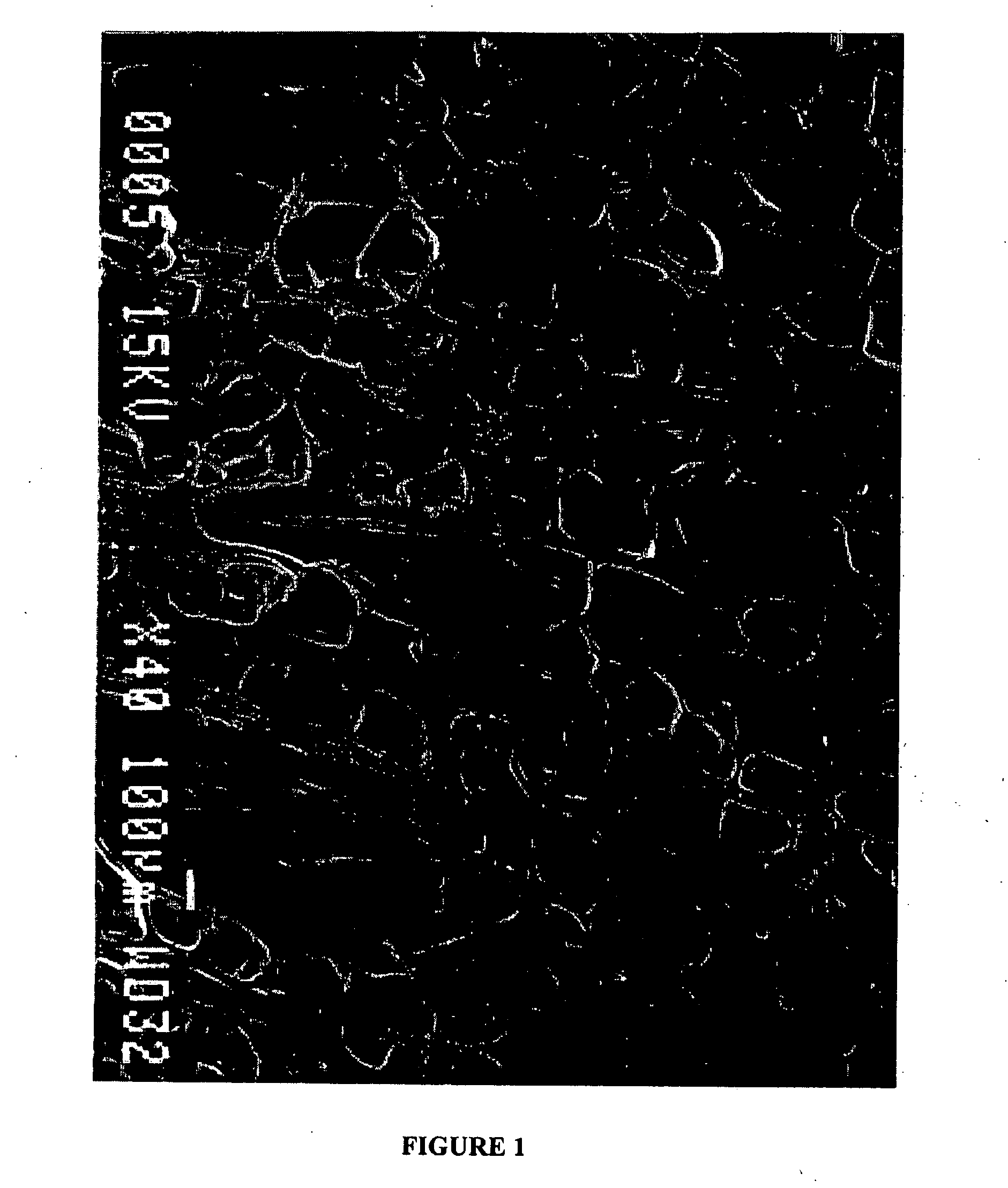
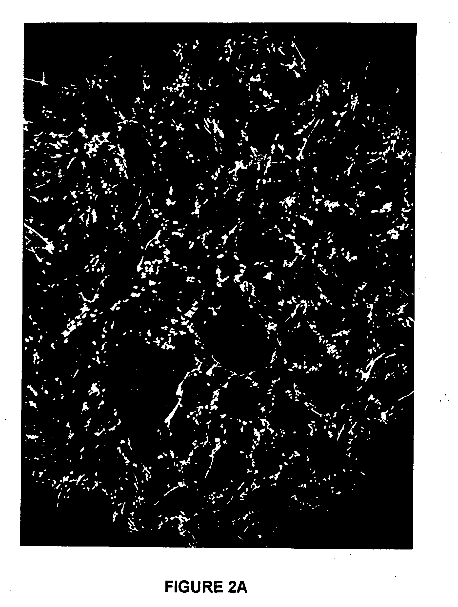
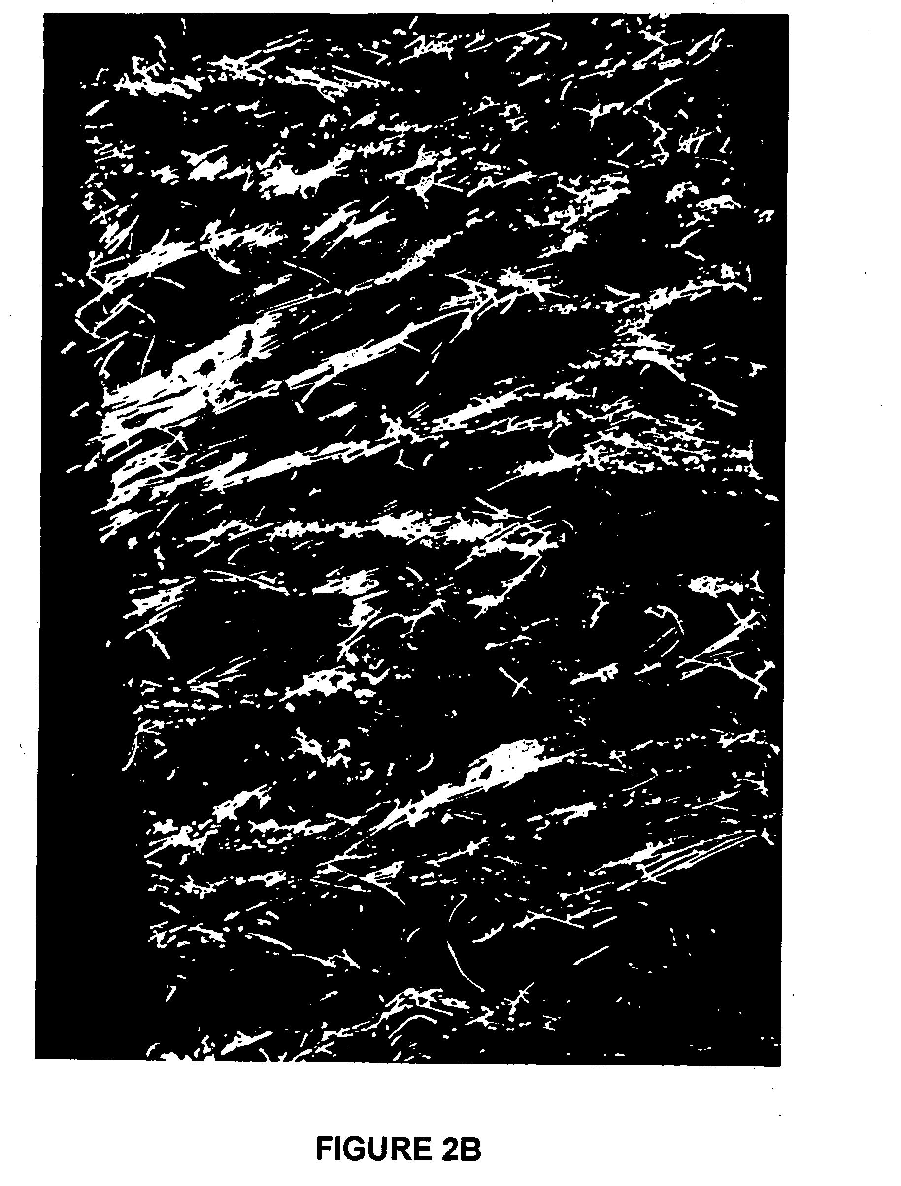
Image

Examples
example 1
Method of Producing a 10% Chopped PGA Fiber-Reinforced, Porous, Biodegradable Implant
[0064] To manufacture a 70 volume % porous, 10 volume % chopped PGA fiber-reinforced, 75:25 poly(D,L-lactide-co-glycolide) (D,L-PLG) wafer, the following procedure was used. First, 1.38 g of 75:25 D,L-PLG (Mw=95,000 Da, intrinsic viscosity=0.76) was dissolved in a Teflon beaker using 6.2 mL of acetone. Next, 0.153 g of PGA fibers with a diameter of approximately 15 cm, chopped to an average length of about 2.6 mm, were placed in a scintillation vial. Then, 6.2 mL of ethanol was added to the vial with the fibers. The level of fluid in the vial was marked with a permanent marker. Next, the fibers and ethanol were transferred to a Waring blender with an additional 20 mL of ethanol. The mixture was blended on setting 2 for a period of 1 minute. The fiber and ethanol mixture was then added back into the scintillation vial, and the ethanol was decanted until the height of the mixture decreased to the ma...
example 2
Mechanical Testing to Show the Influence of Fiber Orientation on the Mechanical Properties of Porous, Biodegradable Implants
[0068] To make porous wafers with reinforcing fibers oriented preferentially in one direction, the manufacturing method described in the detailed description of the preferred embodiments and Example 1 was used. The addition “cyl” is attached to those implants made using this method, to indicate the cylindrical molds that were used. To make implants with reinforcing fibers oriented in two directions, a plate-like mold was used with dimensions 6 cm×6 cm×3 mm thick and the gel was flattened to fit the sides of the mold before the final vacuum step. The addition “flat” is attached to the implants made using this method, and indicates the flat, plate-like form of the cured wafer.
[0069] The matrix polymer used was a random copolymer of 75:25 poly(D,L-lactide-co-glycolide) and the fibers were poly(glycolide) with a diameter of about 15 μm and an average length of a...
example 3
Mechanical Testing to Show the Influence of Increasing Levels of Chopped PGA Fiber-Reinforcement on Porous, Biodegradable Implants
[0079] Implants were made according to the method described in the detailed description of embodiments and in Example 1. The matrix polymer used was a random copolymer of 75:25 poly(D,L-lactide-co-glycolide) and the fibers were poly(glycolide) with a diameter of about 15 μm and an average length of about 2.5 mm. Implants were made with fiber volume fractions of 0%, 5%, 10%, 15%, and 20%. Cylindrical samples of about 6 mm diameter and 3 mm length were prepared according to the description in Example 1. The parallel plate compression test method described in Example 2 was used to measure the mechanical properties of the cylindrical wafers. The wafers were tested parallel to the direction of preferential orientation of the fibers.
[0080] From the stress versus strain data and postprocessing analysis, the Young's modulus and yield stress of the samples were...
PUM
| Property | Measurement | Unit |
|---|---|---|
| Fraction | aaaaa | aaaaa |
| Fraction | aaaaa | aaaaa |
| Length | aaaaa | aaaaa |
Abstract
Description
Claims
Application Information