[0011] The present invention involves the fabrication and use of biocompatible materials (synthetic, natural, or a combination of both) to replace at least a portion of the natural
intervertebral disc. The implantable materials preferably are operative in three stages, which can have different functions and
modes of action. The first stage facilitates
percutaneous delivery into the intervertebral disc; the second stage provides mechanical and material properties that mimic substantially those of the natural disc or portion thereof that it is replacing; and the third stage enables
drug delivery to and regeneration of cells within the remaining portion of the disc. After implantation into the disc void in the first stage, the material is transitioned into its second stage. The second stage includes filling the disc void, and also includes creating an environment that acts as a load-bearing frame structure while being conducive to promoting disc
cell regeneration and
tissue ingrowth by providing mechanical and material properties that mimic closely those of the natural disc or portion thereof that the material is replacing. In the third stage, one or more
cell binding agents, growth factors, and / or drugs interact with the remaining portion of the disc to support
tissue ingrowth and to achieve a probability of biological mimicking higher than that achieved by the second stage.
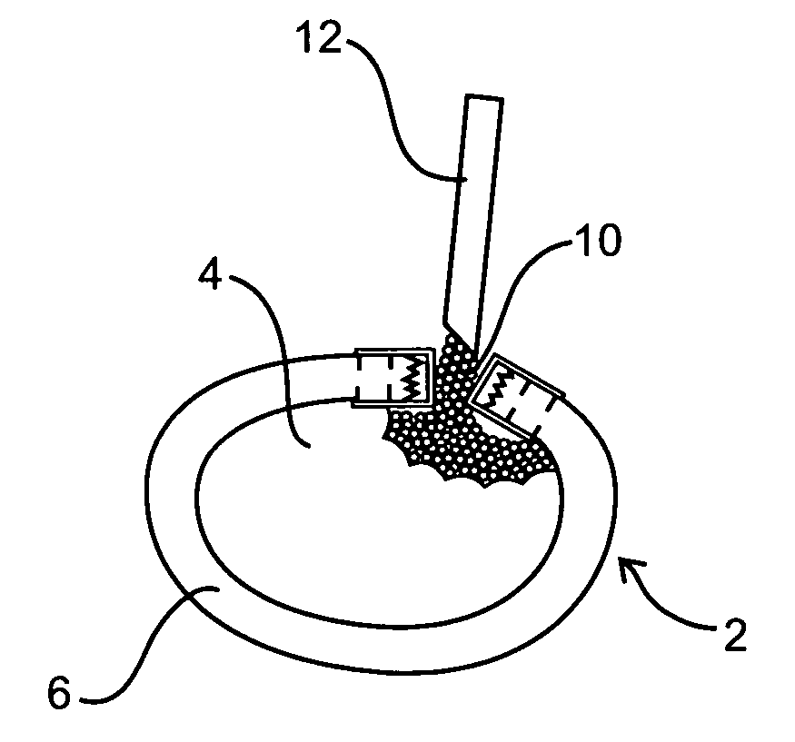
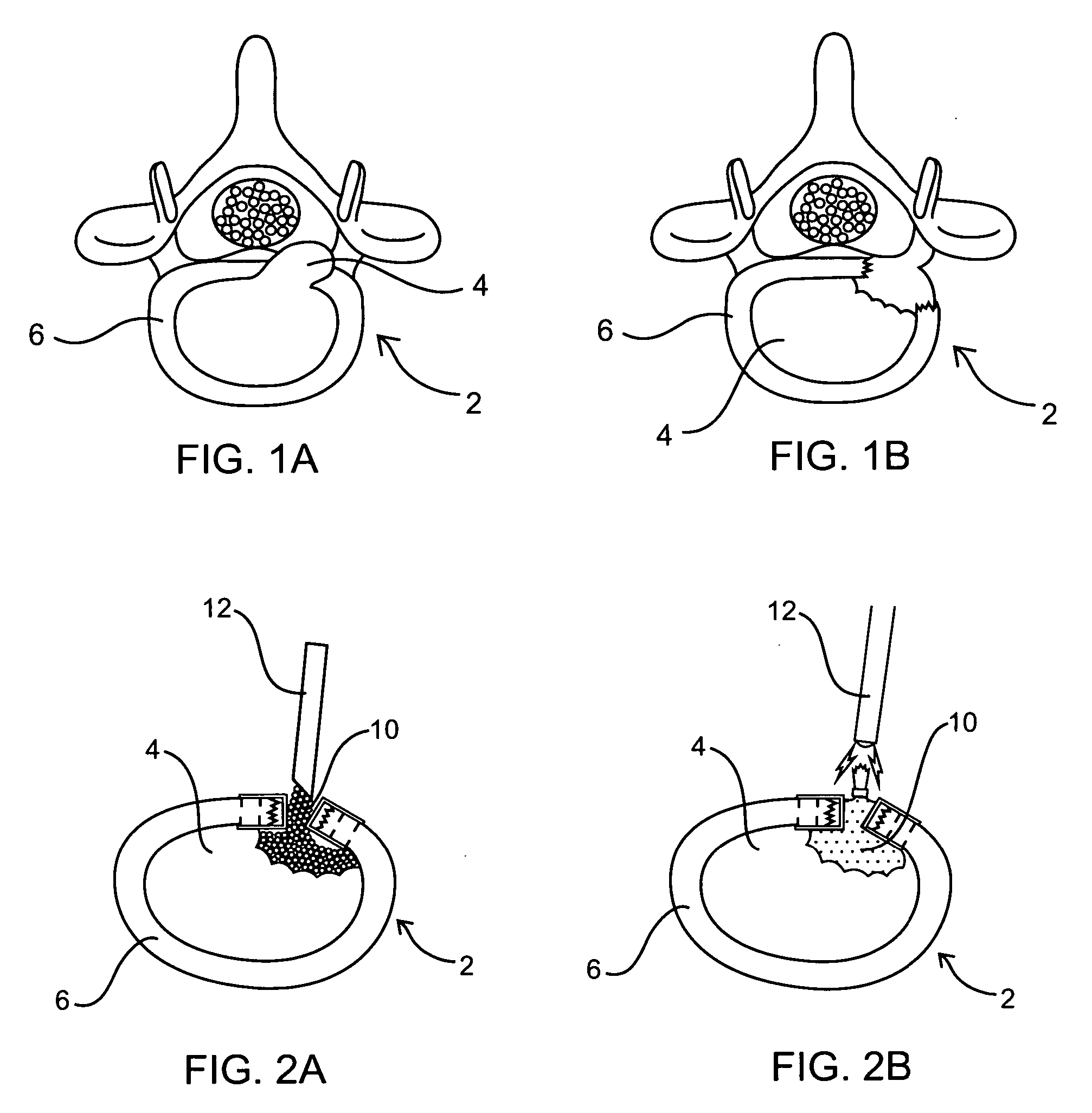
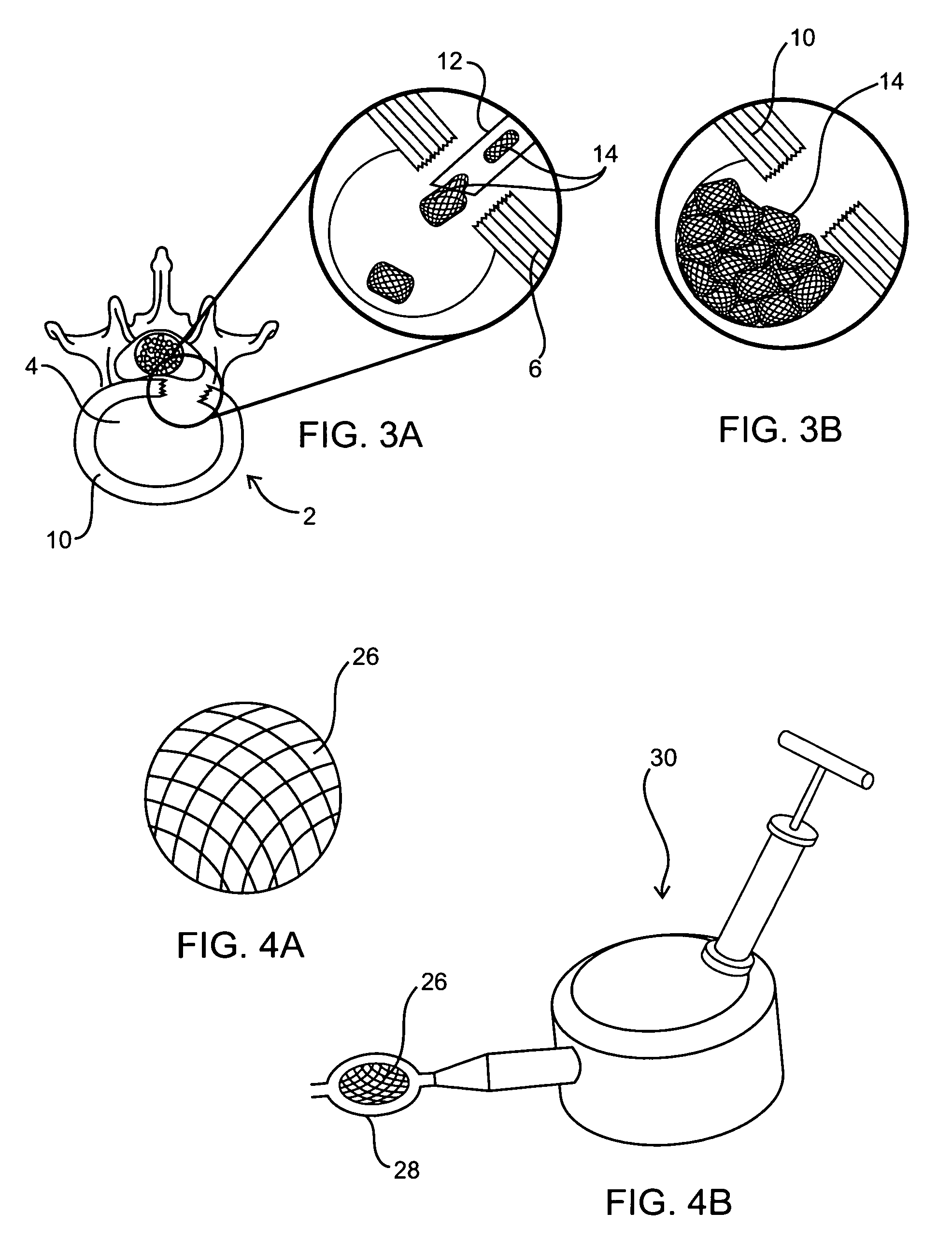
[0012] The nucleus of a herniated spinal disc is extruded and is displaced from its
normal position within the boundaries of its outer
fibrous tissue, the annulus. Herniation puts pressure on a portion of the
spinal cord and on the corresponding nerves and results in considerable pain. In an embodiment of the present invention, a
biocompatible material is injected percutaneously into the defective region and acts as a substitute for the extruded nucleus, so as to prevent further degeneration of the nucleus.
[0015] The present invention is particularly suitable for replacing a portion of the intervertebral disc nucleus. In comparison to
total disc replacement, an injectable disc nucleus has numerous advantages. Since only the nucleus is being replaced, the procedure is considerably
less invasive, easier to approach and perform, and easier to revise in the event that additional
surgery becomes necessary. The risk of permanent
nerve injury is lower and no fixation components are required since the
implant is not designed to be affixed to the vertebrae. Further, by replacing only the nucleus, this treatment method could potentially enable the reestablishment of the biomechanical properties of the diseased or degenerative disc while preserving the functions of the remaining disc tissues (i.e., the disc annulus and vertebral endplates). This is desirable for numerous reasons, most notably in preventing or greatly postponing the
disc degeneration process that generally occurs from traditional
surgical methods. Other advantages include the maintenance of
range of motion and mechanical characteristics, restoration of natural
disc height and spinal alignment, and significant
pain reduction.
[0016] The use of polymers as the
implant material is advantageous over other contemplated materials for various reasons. Because the polymers are at least initially in a flowable or conformable state, they can fill any void of any size and shape. In turn, because the entirety of a void may be filled, the stresses on the
implant are ideally distributed resulting in a more stable disc. The implants may be further designed to have mechanical properties of a natural disc nucleus, including sharing a substantial portion of the disc's
compressive load and restoring the
normal load distribution while avoiding excessive wear on the endplate-implant interface.
[0017] The implant materials (whether used as a filler material and / or a casing material which contains or covers the filler material) of the present invention may include one or more polymers in any of the below-described forms (e.g., hydrogels, microgel particles, foam, cords, etc.) or may be a
polymer precursor (e.g., monomers, oligomers) which, upon reacting with
polymerization initiators or crosslinkers, form a
polymer. These implantable materials or equivalents thereof may be configured to have any material and / or mechanical properties to restore the disc
anatomy and function to its original state or as close to its original state as possible. For example, implants could be a mixture of biodegradable and non-biodegradable materials. More specifically, over time the biodegradable material could accelerate the encapsulation of appropriate cell lines that produce
extracellular matrix proteins such as collagen, while the non-biodegradable material would support mechanical loading of the disc until the ingrowth of tissue was sufficient to maintain the integrity of the disc. To this end, the
porosity of the implant can be selected to time the
biodegradation process accordingly as well as to facilitate the biological functions of the nucleus, including but not limited to fluid
diffusion, nutrients transport, and
metabolite removal through the disc.

