
Porous tissue scaffoldings for the repair or regeneration of tissue

Inactive Publication Date: 2001-10-25
ETHICON ENDO SURGERY INC
View PDF0 Cites 79 Cited by
  • Summary
  • Abstract
  • Description
  • Claims
  • Application Information

AI Technical Summary

Benefits of technology

[0009] The present invention provides a biocompatible gradient foam that has a substantially continuous transition in at least one characteristic selected from the group consisting of composition, stiffness, flexibility, bioabsorption rate pore architecture and / or microstructure. This gradient foam can be made from a blend of absorbable polymers that form compositional gradient transitions from one polymeric material to a second polymeric material. In situations where a single chemical composition is sufficient for the application, the invention provides a biocompatible foam that may have microstructural variations in the structure across one or more dimensions that may mimic the anatomical features of the tissue (e.g. cartilage, skin, bone etc.).
[0012] The present invention also provides a method for the repair or regeneration of tissue contacting a first tissue with a gradient foam at a location on the foam that has appropriate properties to facilitate the growth of said tissue. The concept of a continuous transition in physical properties, chemical composition and / or microstructural features in the porous scaffold (foam) can facilitate the growth or regeneration of tissue. These foam structures are particularly useful for the generation of tissue junctions between two or more different types of tissues. For a multi-cellular system in the simplest case, one cell type could be present on one side of the scaffold and a second cell type on the other side of the scaffold. Examples of such regeneration can be (a) skin: with fibroblasts on one side to regenerate dermis, and keratinocytes on the other to regenerate epidermis; (b) vascular grafts: with an endothelial layer on the inside of the graft and a smooth muscle cell layer on the outside.

Problems solved by technology

However, the above techniques have limitations in producing a scaffold with a gradient structure.
Further, it is the limitation of prior art to make 3D scaffolds that have the ability to control the spatial distribution of various pore shapes.
However, the interface between the cartilage and bone in the human body is not a discrete junction of two dissimilar materials with an abrupt change in anatomical features and / or the mechanical properties.
In this technique which is quite cumbersome, a porous membrane is first prepared by drying a polymer solution containing leachable salt crystals.
One of the major weaknesses of the prior art regarding three-dimensional porous scaffolds used for the regeneration of biological tissue like cartilage is that their microstructure is random.
Further, current scaffolds do not provide adequate nutrient and fluid transport for many applications.
Finally, the laminated structures are not completely integrated and subjected to delamination under in vivo conditions.

Method used


Image

  • Porous tissue scaffoldings for the repair or regeneration of tissue
  • Porous tissue scaffoldings for the repair or regeneration of tissue
  • Porous tissue scaffoldings for the repair or regeneration of tissue

Examples


example 1

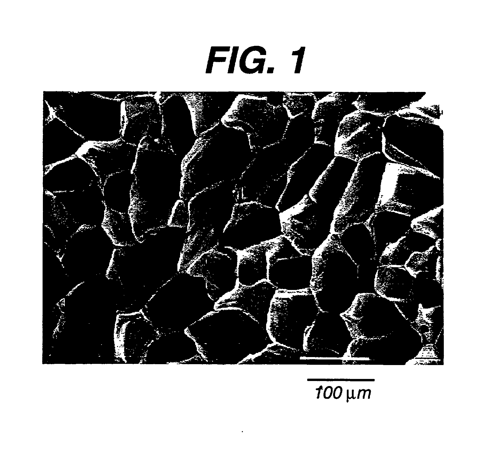
[0098] Preparation of a Foam With Random Microstructure (No Preferred Architecture)

[0099] Step A. Preparing 5% wt. / wt. Homogeneous Solution of 35 / 65 PCL / PGA in 1,4-Dioxane

[0100] A 5% wt. / wt. polymer solution is prepared by dissolving 1 part of 35 / 65 PCL / PGA with 19 parts of the solvent 1,4-dioxane. The 35 / 65 PCL / PGA copolymer was made substantially as described in Example 8. The solution is prepared in a flask with a magnetic stir bar. For the copolymer to dissolve completely, it is recommended that the mixture is gently heated to 60.+-.5.degree. C. and continuously stirred for a minimum of 4 hours but not exceeding 8 hours. A clear homogeneous solution is then obtained by filtering the solution through an extra coarse porosity filter (Pyrex brand extraction thimble with fritted disc) using dry nitrogen to help in the filtration of this viscous solution.

[0101] Step B. Lyophilization

[0102] A laboratory scale lyophilizer--Freezemobile 6 of VIRTIS was used in this experiment. The freez...

example 2

[0109] Preparation of a Foam With Vertical Channels

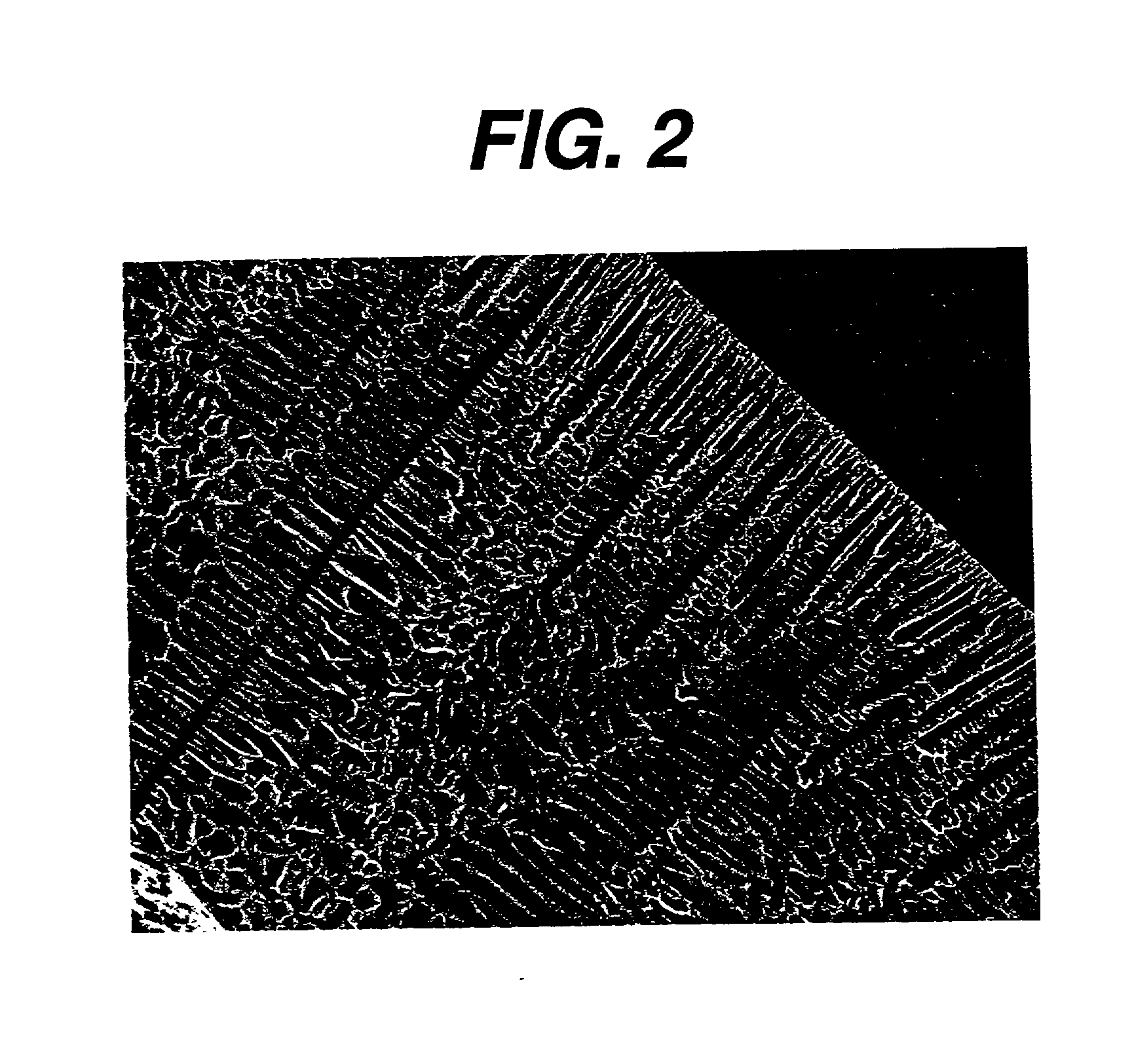
[0110] This example describes the making of a 35 / 65 PCL / PGA foam with vertical channels that would provide pathways for nutrient transport and guided tissue regeneration.

[0111] We used a FTS Dura Dry Freeze dryer with computer control and data monitoring system to make this foam. First step in the preparation of this foam was to generate a homogeneous solution. A 10% wt. / wt. homogeneous solution of 35 / 65 PCL / PGA was made in a manner similar to that described in Example 1, Step A. The polymer solution was carefully filled into a dish just before the actual start of the cycle. The dish weighed 620 grams, was optical glass 5.5 mm thick, and cylindrical with a 21 cm outer diameter and a 19.5 cm inner diameter. The lip height of the dish was 2.5 cm. Next the following steps are followed in sequence to make a 2 mm thick foam with the desired architecture:

[0112] (i). The solution filled dish was placed on the freeze dryer shelf that was pr...

example 3

[0117] Architecturally Gradient Foam

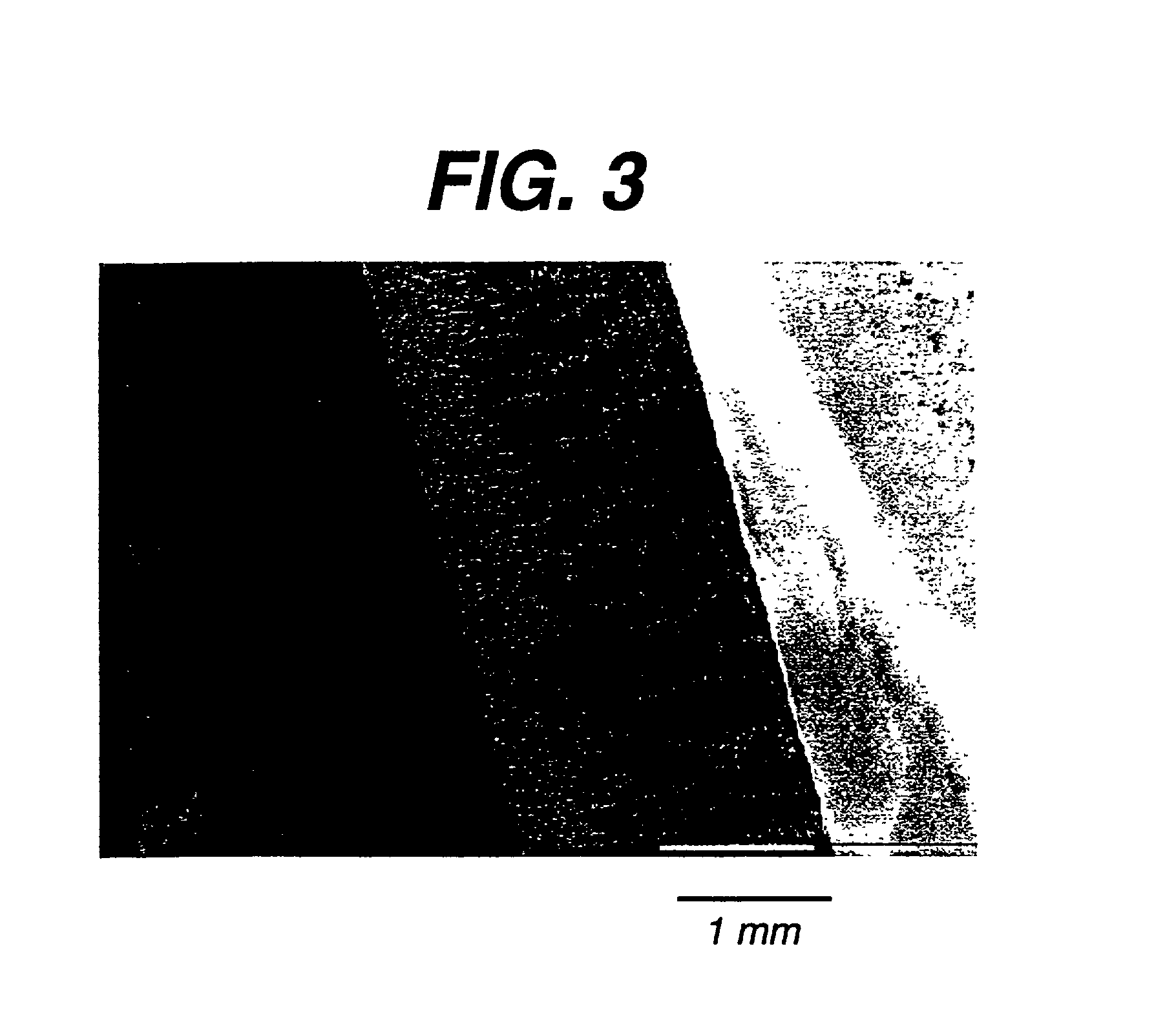
[0118] This example describes the making of a foam that has a gradient in foam morphology as shown in FIG. 3 using a 10% solution of 35 / 65 .epsilon.-caprolactone-co-glycolide. The method used to make such a foam is similar to the description given in Example 2 with one difference. In step (ii) of the lyophilization process the time for which the solution is kept at the freezing step is 30 minutes.

[0119] FIG. 3 is a scanning electron micrograph of a cross section of this foam. Note the variation in the pore size and pore shape through the thickness of the foam.


PUM

PropertyMeasurementUnit
Fractionaaaaaaaaaa
Percent by massaaaaaaaaaa

Abstract

The present patent describes a three-dimensional interconnected open cell porous foams that have a gradient in composition and / or microstructure through one or more directions. These foams can be made from a blend of absorbable and biocompatible polymers that are formed into foams having a compositional gradient transitioning from predominately one polymeric material to predominately a second polymeric material. These gradient foams are particularly well suited to tissue engineering applications and can be designed to mimic tissue transition or interface zones.

Description

[0001] The present invention relates generally to the field of tissue repair and regeneration. More particularly the present invention relates to porous biocompatible bioabsorbable foams that have a gradient in composition and / or microstructure that serve as a template for tissue regeneration, repair or augmentation.[0002] Open cell porous biocompatible foams have been recognized to have significant potential for use in the repair and regeneration of tissue. Early efforts in tissue repair focused on the use of amorphous biocompatible foam as porous plugs to fill voids in bone. Brekke, et al. (U.S. Pat. No. 4,186,448) described the use of porous mesh plugs composed of polyhydroxy acid polymers such as polylactide for healing bone voids. Several attempts have been made in the recent past to make TE scaffolds using different methods, for example U.S. Pat. No. 5,522,895 (Mikos) and 5,514,378 (Mikos, et al.) using leachables; U.S. Pat. No. 5,755,792 (Brekke) and U.S. Pat. No. 5,133,755 (...

Claims


Application Information

Patent Timeline
IPC IPC(8): A61F2/00A61F2/02A61F2/06A61F2/28A61F2/30A61L27/18A61L27/38A61L27/56A61L31/06A61L31/14
CPCA61F2/06A61F2/28A61F2/30756A61F2002/30004A61F2002/30011A61F2002/30014A61F2002/30018A61F2002/30032A61F2002/30062A61F2002/30677A61F2002/30766A61F2002/30784A61F2002/3092A61F2210/0004A61F2250/0014A61F2250/0018A61F2250/0023A61F2250/0029A61F2250/003A61F2250/0067A61L27/18A61L27/3817A61L27/56A61L31/06A61L31/146C08L67/04Y10S514/945Y10S623/915
Inventor VYAKARNAM, MURTY N.ZIMMERMAN, MARK C.SCOPELIANOS, ANGELO GEORGEROLLER, MARK B.GORKY, DAVID V.
Owner ETHICON ENDO SURGERY INC
Learn More