

Spark plug
- Summary
- Abstract
- Description
- Claims
- Application Information
AI Technical Summary
Benefits of technology
Problems solved by technology
Method used
Image

Examples
first embodiment
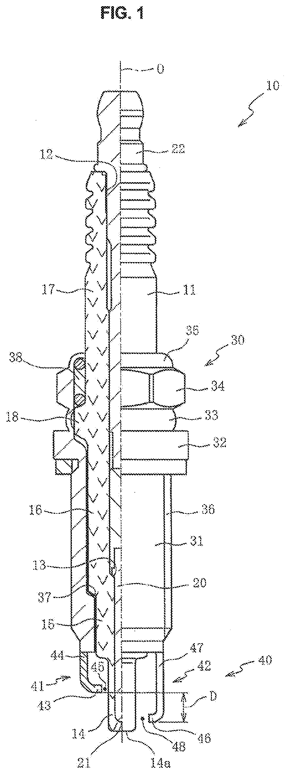
[0021]The following describes exemplary embodiments of the present invention, with reference to the attached drawings. FIG. 1 is a half sectional view of a spark plug 10 wherein the spark plug 10 has an axis O serving as a border of the half sectional view. In FIG. 1, a lower side in the drawing is referred to as a front end side of the spark plug 10, and an upper side in the drawing is referred to as a rear end side of the spark plug 10. This is same for FIGS. 3A, 3B, 4A, and 4B. As shown in FIG. 1, the spark plug 10 includes an insulator 11, a central electrode 20, a metal shell 30, and ground electrodes 40.
[0022]The insulator 11 is a bottomed tubular member made of alumina sufficient in insulation performance and mechanical characteristics under high temperature. The insulator 11 includes a hole 12 extending along the axis O and having a circular cross section. The hole 12 is open at a rear end of the insulator 11, and is closed at a front end of the insulator 11. The insulator ...
second embodiment
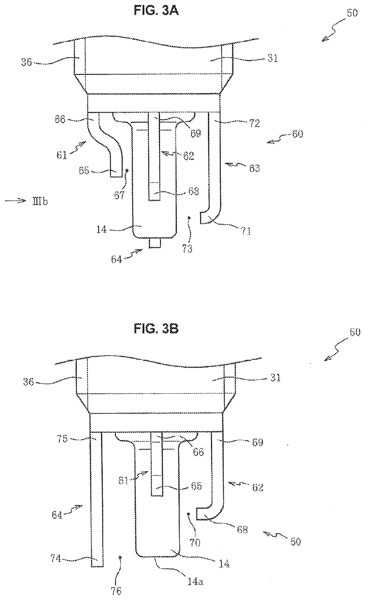
[0050]FIG. 3A is a side view of a spark plug 50 according to the FIG. 3B is a side view of the spark plug 50 viewed in a direction of an arrow IIIb shown in FIG. 3A. Each of FIGS. 3A and 3B is drawn omitting its rear-end-side section, and each of FIGS. 4A and 4B is drawn similarly.
[0051]As shown in FIGS. 3A and 3B, the spark plug 50 includes the ground electrodes 60 each of which is a rod member made of metal such as nickel-base alloy and is connected to the front end section 31 of the metal shell 30 (see FIG. 1). The ground electrodes 60 are composed of a first electrode 61, a second electrode 62, a third electrode 63, and a fourth electrode 64 each of which has a rectangular cross section and is disposed parallel with the axis O.
[0052]The first electrode 61 includes a first end 65 and a second end 66, wherein the first end 65 is positioned frontward with respect to the second end 66 connected to the metal shell 30. The first electrode 61 includes an axially central section bent t...
third embodiment
[0075]Although according to the second or third embodiment the four ground electrodes 60 or 90 are arranged at equal intervals in the circumferential direction, the present invention is not limited to that. The circumferential intervals of the ground electrodes may be appropriately modified.
DESCRIPTION OF THE SIGNS
PUM
 Abstract
Description
Claims
Application Information