Trajectory-based guidance of a motor vehicle

a technology of trajectory and motor vehicle, which is applied in the direction of vehicle position/course/altitude control, process and machine control, instruments, etc., can solve the problems of inconvenient quality of such a trajectory, and achieve the effect of maximizing safety distance, enhancing comfort of motor vehicle transportation, and maximizing safety distan

Active Publication Date: 2018-12-20
ROBERT BOSCH GMBH
View PDF0 Cites 5 Cited by
  • Summary
  • Abstract
  • Description
  • Claims
  • Application Information

AI Technical Summary

Benefits of technology

[0010]In a second variant, the motor vehicle is moved on a predefined maneuvering area, the optimization including a maximization of a minimum distance between an outline of the motor vehicle and a boundary of the maneuvering area. The maneuvering area may be indicated, for example, as a planning area and, in particular, may have a rectangular shape. Alternatively, the maneuvering area may also be defined in terms of its shape and size on the basis of structural or statutory conditions. During travel along one of the trajectories, different points of the outline of the motor vehicle may each come close to a boundary of the maneuvering area. By maximizing the minimum distance, a compensation may be achieved, so that, overall, the motor vehicle is surrounded by a maximized safety distance during the travel along the second trajectory. The risk of touching an object which lies at the boundary of the maneuvering area, or a moving object on the maneuvering area which may not be able to easily get out of the way between the boundary and the motor vehicle, may be reduced in this way.
[0011]In a third variant, an object in the area of the motor vehicle is scanned during the driver-controlled movement of the motor vehicle, the optimization including a maximization of a minimum distance between an outline of the motor vehicle and the object. In a similar way, as described above, a safety distance around the motor vehicle may be maximized in this way.
[0012]Overall, the optimization may be carried out in such a way that the travel along the second trajectory by a person within or outside the motor vehicle is perceived as elegant and reliable. An acceptance of the method, in particular by a driver of the motor vehicle, may be enhanced as a result. In addition, loads on the motor vehicle, for example during a change in direction, during negotiating a curve, during accelerating or decelerating, may be minimized.
[0013]In one fourth variant, the optimization includes a circumvention of an object which lies on the first trajectory. Such an object may include an obstacle such as a manhole cover, a pothole, or a potentially slippery roadway marking. A comfort of the transport of the motor vehicle may be enhanced as a result and a load on the motor vehicle may be reduced.
[0014]In one fifth variant, the optimization includes a maximization of an angle at which an object on the second trajectory is driven over. The object may be, for example, a threshold, a channel, or a curb. It may be sought that the angle is approximately 90°. In particular, it may be sought that wheels of one axle of the motor vehicle roll over the object essentially simultaneously. A rolling movement of the motor vehicle, which may be induced by the object being driven over non-simultaneously, may be avoided as a result. A lifting or dropping movement of the motor vehicle may be perceived by a person on board as less unpleasant. In addition, the risk of damage to a tire or a wheel rim may be reduced.

Problems solved by technology

The quality of such a trajectory is frequently not cogent, however, due to a multitude of possible influence factors.

Method used


Image

  • Trajectory-based guidance of a motor vehicle
  • Trajectory-based guidance of a motor vehicle
  • Trajectory-based guidance of a motor vehicle

Examples


Embodiment Construction

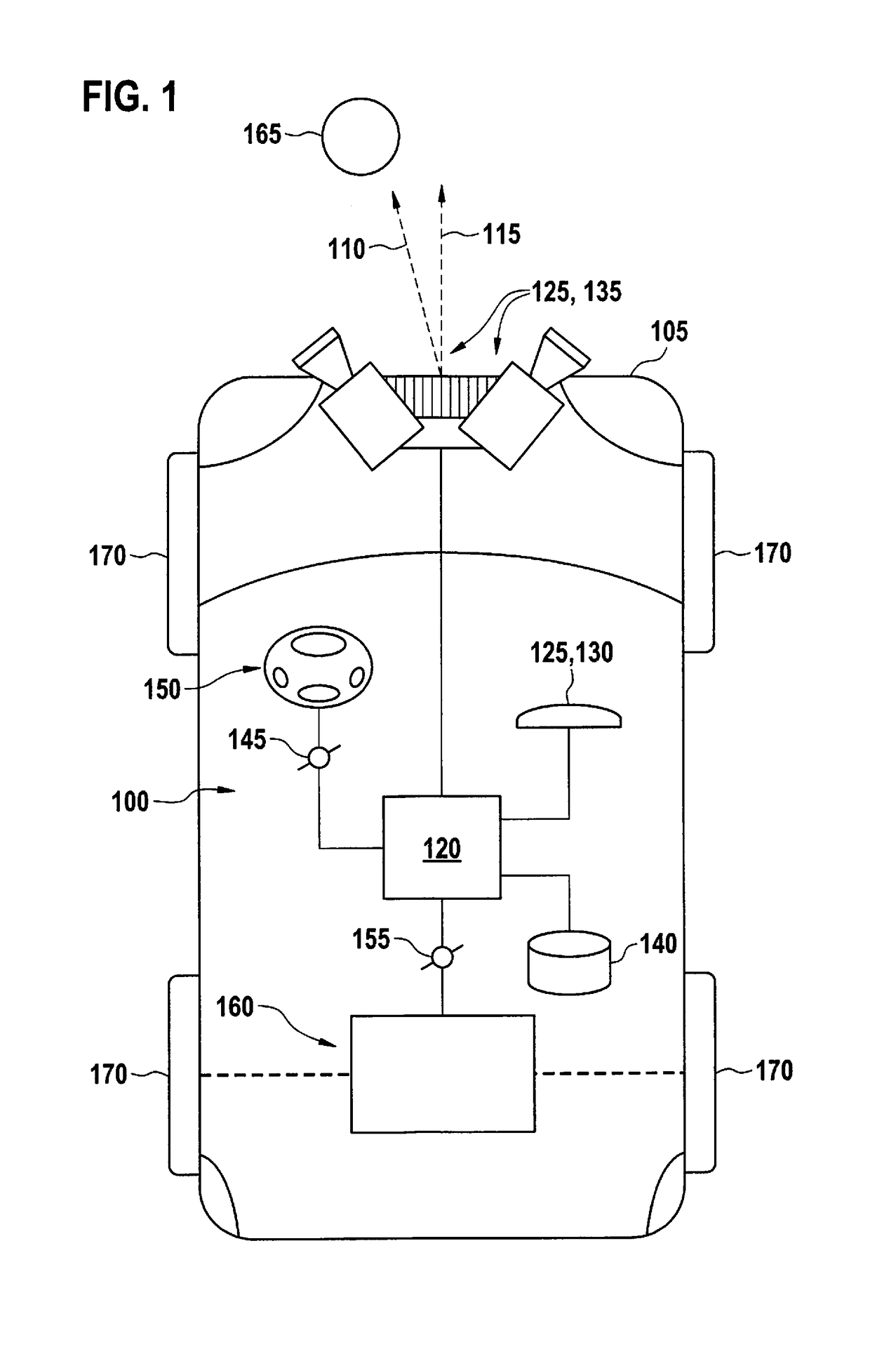
[0024]FIG. 1 shows a device 100 on board a motor vehicle 105. Motor vehicle 105 may include a passenger car, although, in other specific embodiments, the motor vehicle may also include, for example, a commercial vehicle such as a truck. Device 100 is configured for determining a first trajectory 110 which motor vehicle 105 describes while it is steered by a driver, and for optimizing first trajectory 110 into a second trajectory 115.

[0025]Device 100 includes a processing unit 120, at least one scanning unit 125 which may be formed, for example, by a positioning unit 130 or a surroundings detection unit 135, and one memory unit 140. Optionally, a first interface 145 to a lateral control 150 or a second interface 155 to a longitudinal control 160 of motor vehicle 105, or both, may be provided.

[0026]Scanning unit 125 is configured for determining first trajectory 110 of motor vehicle 105. First trajectory 110 runs between a starting point and an end point and usually performs a maneuve...


PUM


Abstract

A method includes determining a first trajectory of the motor vehicle during a driver-controlled movement of the motor vehicle; determining a second trajectory on the basis of the first trajectory; and storing the second trajectory for the subsequent driver-independent guidance of the motor vehicle on the second trajectory. In this case, the second trajectory includes an optimization of the first trajectory.

Description

RELATED APPLICATION INFORMATION[0001]The present application claims priority to and the benefit of German patent application no. 10 2017 210 171.7, which was filed in Germany on Jun. 19, 2017, the disclosure which is incorporated herein by reference.FIELD OF THE INVENTION[0002]The present invention relates to the driver-independent guidance of a motor vehicle. In particular, the present invention relates to the guidance of the motor vehicle along a predetermined trajectory.BACKGROUND INFORMATION[0003]A motor vehicle includes a driver assistance function which is to relieve the driver during the guidance of the motor vehicle. For different purposes, numerous proposals have been made for driver assistance functions. For example, a parking or unparking process of a motor vehicle may be actively assisted or even autonomously carried out with the aid of a corresponding driver assistance system.[0004]Patent document DE 10 2014 014 219 A1 relates to a method for carrying out a parking proc...

Claims


Application Information

Patent Timeline
Patent Type & Authority Applications(United States)
IPC IPC(8): B60W30/06B62D15/02G05D1/02
CPCB60W30/06B62D15/0285G05D1/0212G05D1/0231B60W2550/10B60W2710/20G05D2201/0213B60W30/08B62D15/028B60W2554/00
Inventor OPPOLZER, LUKASBRETTSCHNEIDER, THOMAS
Owner ROBERT BOSCH GMBH
Why Eureka
Try Eureka