

Overhead Wire Damper
Active Publication Date: 2018-12-20
FURUKAWA ELECTRIC POWER SYST +1
View PDF5 Cites 2 Cited by
- Summary
- Abstract
- Description
- Claims
- Application Information
AI Technical Summary
Benefits of technology
The patent is about a device that reduces the lifting force caused by wind or other factors on overhead lines. This device helps to keep the lines upright and steady, which can increase their reliability and safety.
Problems solved by technology
Conventionally, in overhead lines such as a power transmission line and a ground wire, when snow accretes on an overhead line, the overhead line twists by rotating due to the dead weight of the snow which accretes on the overhead line, the snow develops into a cylinder shape while rotating, and a disorder such as occurrence of breaking occurs.
Method used
View moreImage
Smart ImageViewing Examples

Examples
embodiment
[0022]Hereinafter, an embodiment of the present disclosure will be described specifically with reference to the accompanying drawings.
Login to View More PUM
 Abstract
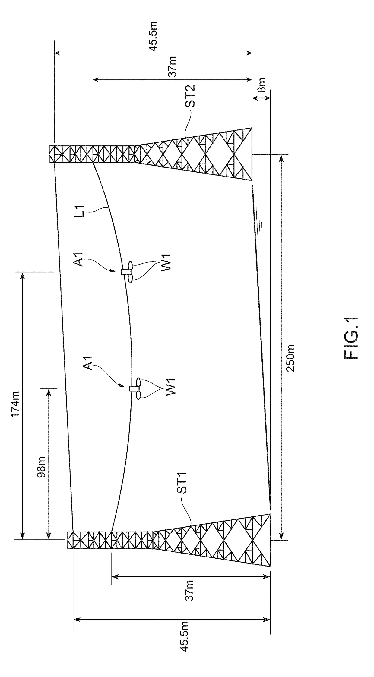
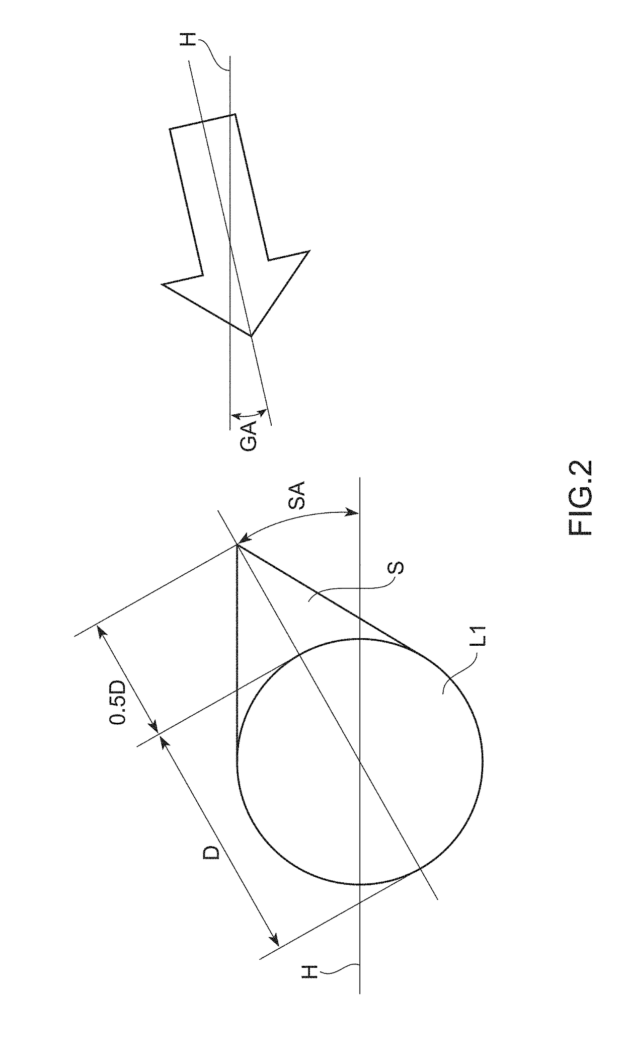
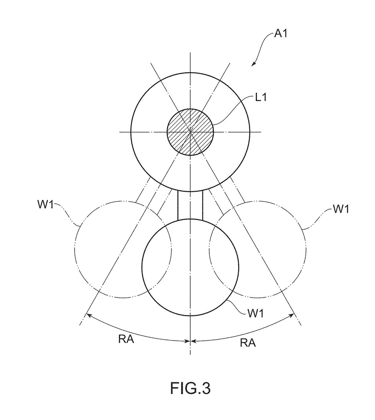
An overhead line damper capable of suppressing a lift force that an overhead line receives due to wind is provided. A damper 1 for an overhead line that is provided at an overhead line L2 includes a clamping mechanism (a pair of hinge pieces 21a and 21b) that is fitted to an outer circumferential surface of the overhead line L2, and a rotary member 4 with a lower part attached to weights 3a and 3b, and an upper part rotatably attached to the clamping mechanism, and the clamping mechanism has a regulation part (an opening part 24) that regulates a rotation range of the rotary member 4 so that the weights 3a and 3b rotate within an angle range from ±20 degrees to ±40 degrees inclusive in a vertical direction.
Description
BACKGROUND OF THE DISCLOSUREField of the Disclosure[0001]The present disclosure relates to an overhead line damper that is used in an overhead line such as a power transmission line and a ground wire, and particularly relates to an overhead line damper that inhibits a lift force which the overhead line receives due to wind or the like.Description of the Related Art[0002]Conventionally, in overhead lines such as a power transmission line and a ground wire, when snow accretes on an overhead line, the overhead line twists by rotating due to the dead weight of the snow which accretes on the overhead line, the snow develops into a cylinder shape while rotating, and a disorder such as occurrence of breaking occurs. Accordingly, in order to prevent twisting of the overhead line due to accretion of snow, an overhead line damper is provided at the overhead line.[0003]In such an overhead line damper, a twist prevention damper is used in which a rotary movable part that rotates along outer cir...
Claims
Login to View More Application Information
Patent Timeline
 IPC IPC(8): H02G7/14F16F7/10
CPCH02G7/14F16F7/10H02G7/05F16F7/1022
InventorAIDA, RYOTAHIGASHIDA, SHUICHITAKEDA, KOZONAKAZAWA, SADANORIOUCHI, KATSUHIROIIDA, KENJIMITSUZUKA, HIROAKIHAMADA, YUTA
OwnerFURUKAWA ELECTRIC POWER SYST