
Dental implant system with positive abutment screw locking and retrieval mechanism

a technology of abutment screw and abutment screw, which is applied in the field of dental implant system, can solve the problems of abutment screw being loose over time, abutment screw showing normal fatigue failure life, and insufficient bon

Active Publication Date: 2018-12-27
LEE CHI KEUNG +1
View PDF0 Cites 2 Cited by
  • Summary
  • Abstract
  • Description
  • Claims
  • Application Information

AI Technical Summary

Benefits of technology

The invention is a dental implant system with improved mechanical performance and serviceability. It addresses two major issues: the self-loosening of the abutment screw due to cyclic loads and the difficulty of retrieving the broken abutment screw remnant inside the implant. The new system aims to solve these issues and provide better performance and ease of use for dental implant dentistry.

Problems solved by technology

Some patients do not have sufficient bone after extraction of the tooth, and therefore will require grafting, a type of artificial bone matrix that can be fused with the jaw bone.
One of the major issues of the current implant system is that the abutment screw will become loose over time due to cyclic occlusal loads on the cemented crown or screw-retained cemented crown.
The abutment screw will exhibit a normal fatigue failure life due to cyclic vertical loads on the crown.
The cyclic lateral loads on the crown will cause a joint slip at the contact interface between the abutment screw and the abutment.
This joint slip effect will reduce the prescribed torque on the abutment screw and cause it to self-loosen.
A delayed response will lead to further self-loosening of the abutment screw, bending loads, micro-crack propagation, and subsequent failing due to fatigue.
Another major issue is the retrieval of the broken abutment screw remnant inside of the implant.
This is truly a well-known challenging and time consuming issue in the dental implant dentistry.
As discussed in the previous section, the abutment screw will become loose and fail at some point in time due to fatigue.
The location of breakage or fracture along the abutment screw will dictate the level of difficulty for accessibility and retrievability.
Other abutment screws fail anywhere along the threaded length with limited visibility and tool accessibility.
In addition, there is another risk of damaging the implant internal threads and making the implant non-usable when operating the special tools to retrieve the broken abutment screw.

Method used


Image

  • Dental implant system with positive abutment screw locking and retrieval mechanism
  • Dental implant system with positive abutment screw locking and retrieval mechanism
  • Dental implant system with positive abutment screw locking and retrieval mechanism

Examples


Embodiment Construction

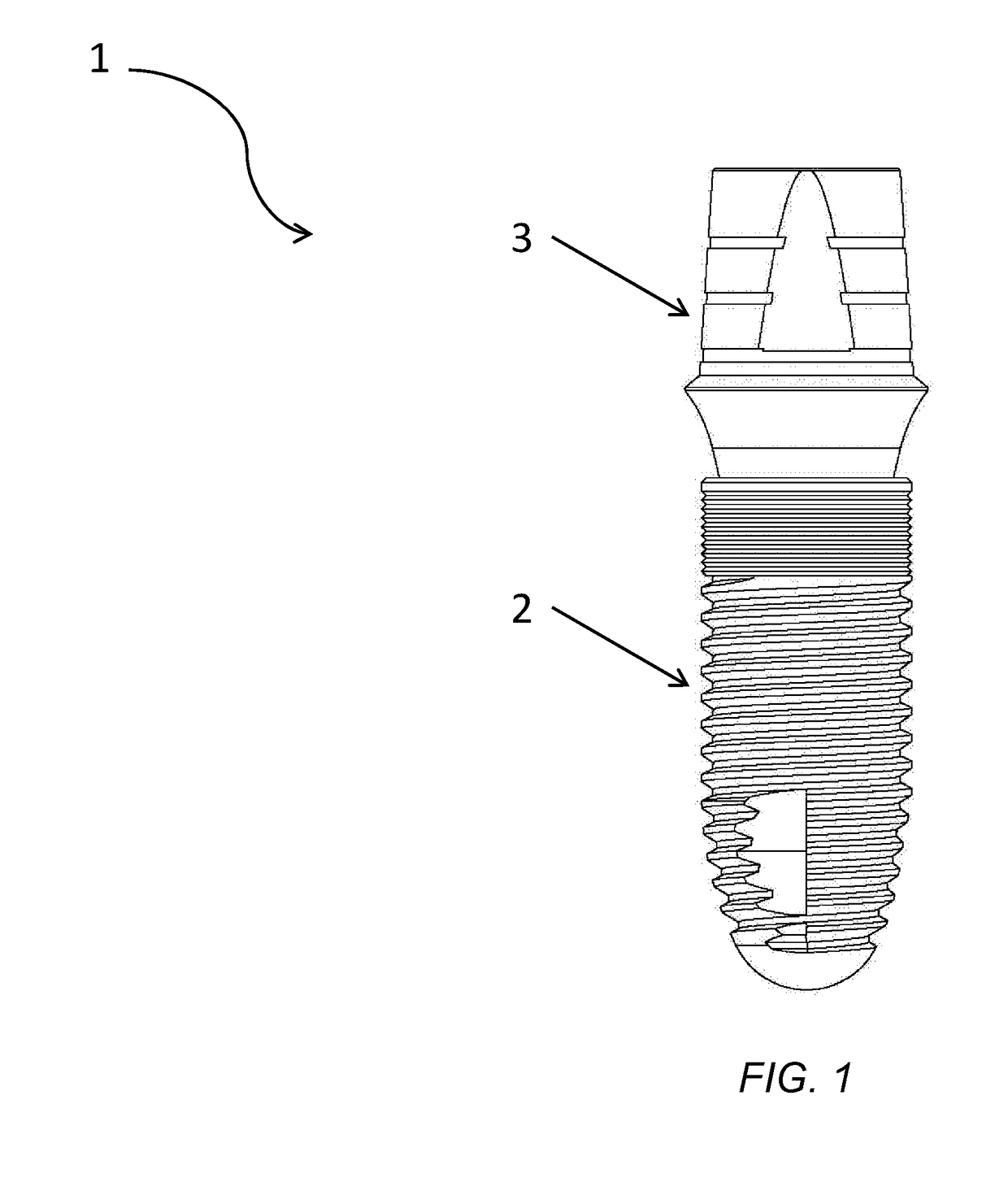
[0014]The inventive principles and concepts are directed to a new dental implant system design that resolves the aforementioned abutment screw self-loosening and broken abutment retrieval issues for single tooth cemented-type crown or single tooth screw-retained-type crown. The inventive principles and concepts also apply to bridge-type implants for multiple teeth and other dental implant applications, such as implant-supported prosthetics, for example.

[0015]The attachment of different crown types onto the abutment has been addressed and discussed previously. In the interest of brevity and for ease of discussion, the following discussion is focused on the mechanical aspects of the individual piece part only.

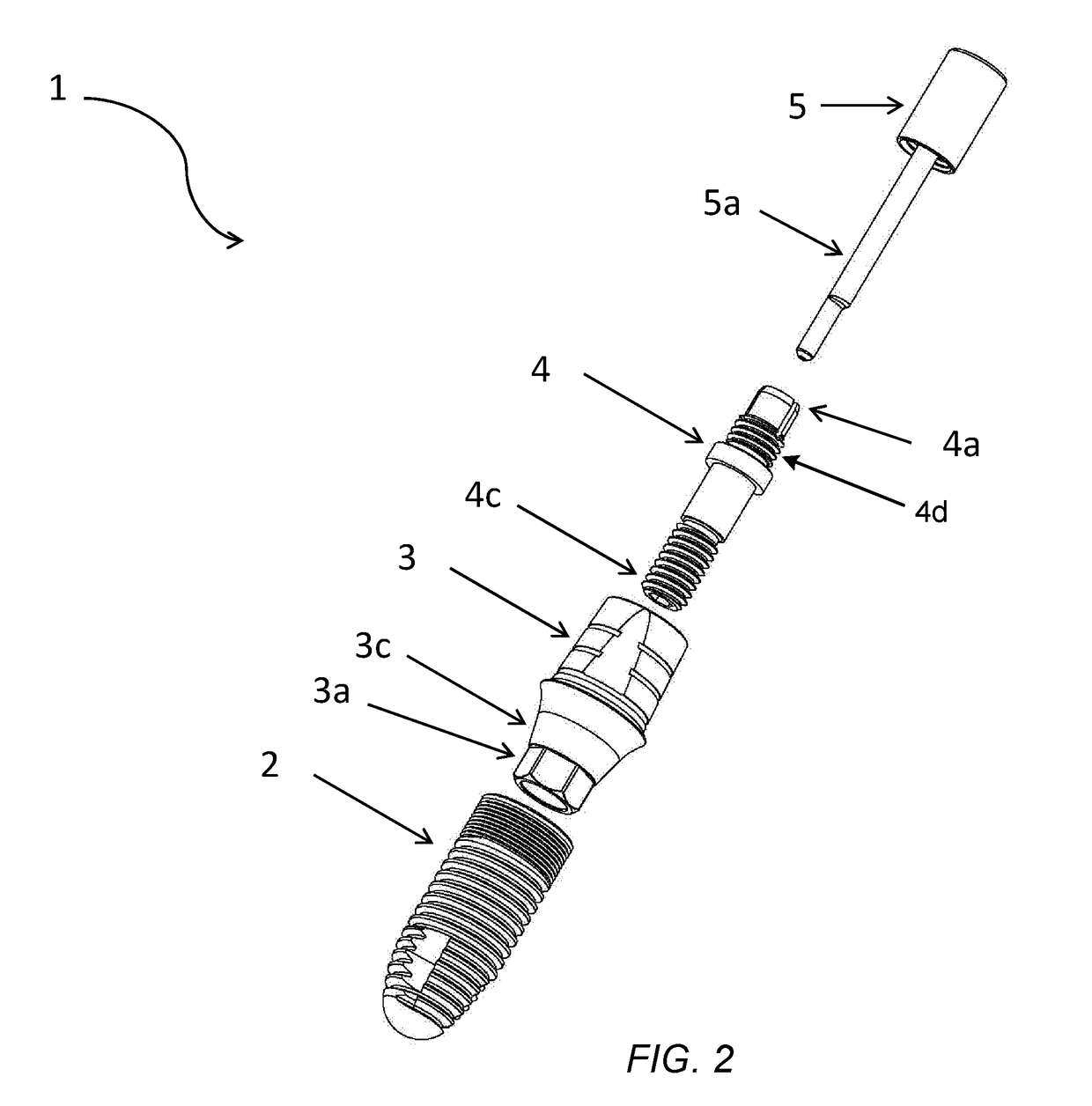
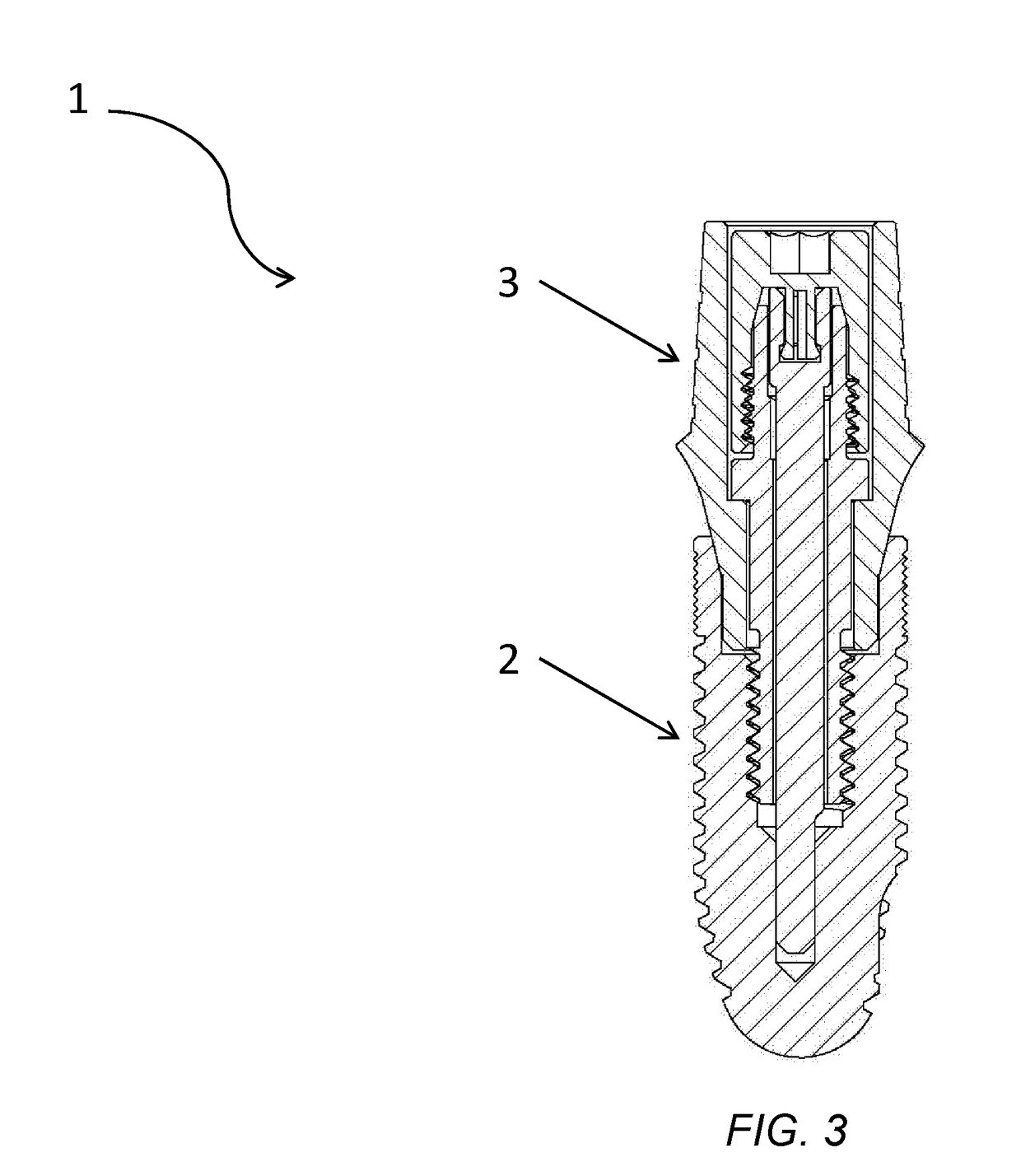
[0016]In accordance with a representative embodiment, the dental implant system comprises four major piece parts, excluding the crown to be cemented on or already fused onto the abutment. The major piece parts comprise one implant, one abutment, one abutment screw, and a sub-asse...


PUM


Abstract

A new dental implant system with positive abutment screw locking and retrieval mechanisms is provided. The abutment screw is positively locked by a keying pin to improve fatigue life. The abutment screw is also equipped with a special feature that greatly improves the retrievability of the broken screw from inside the implant. In addition, the keying pin is designed with a lock nut as a sub-assembly for ease of installation.

Description

CROSS-REFERENCE TO RELATED APPLICATIONS AND PRIORITY CLAIM[0001]This application is a PCT international application that claims priority to, and the benefit of the filing date of, a U.S. provisional application having application Ser. No. 62 / 412,547, filed on Oct. 25, 2016, entitled “DENTAL IMPLANT SYSTEM WITH POSITIVE ABUTMENT SCREW LOCKING AND RETRIEVAL MECHANISMS,” which is incorporated by reference herein in its entirety.TECHNICAL FIELD OF THE INVENTION[0002]The invention relates to a dental implant system with high mechanical performance and serviceability. More importantly, the invention relates to an abutment screw design with positive locking and retrieval mechanisms for improving the screw fatigue life and for allowing easy retrieval of a broken abutment screw remnant inside the implant in the event that the abutment screw breaks.BACKGROUND OF THE INVENTION[0003]Dental implant technology is a mature technology that is becoming increasingly affordable and popular. This is a ...

Claims


Application Information

Patent Timeline
Patent Type & Authority Applications(United States)
IPC IPC(8): A61C8/00
CPCA61C8/0068A61C8/0089A61C8/0074A61C8/0093A61C8/0022A61C8/006A61C8/0071
Inventor LEE, CHI KEUNGNARULA, GURPREET SINGH
Owner LEE CHI KEUNG
Learn More