
Intraocular lenses for presbyopia treatment

a technology of intraocular lenses and presbyopia, applied in the field of diffractive ophthalmic lenses, can solve the problems of crystalline lenses that have only limited ability to change shape, presbyopic eyes often lose the ability to quickly and easily refocus on objects, and crystalline lenses that have lost almost all elastic properties and other problems, to achieve the effect of reducing the risk of cataracts

Active Publication Date: 2018-12-27
AMO GRONINGEN
View PDF0 Cites 15 Cited by
  • Summary
  • Abstract
  • Description
  • Claims
  • Application Information

AI Technical Summary

Benefits of technology

The patent describes an ophthalmic lens with a specific diffractive profile that can be used to improve vision. The lens has a central zone, a peripheral zone, and a middle zone. The central zone includes a first set of two echelettes, while the peripheral zone includes a second set of two echelettes. The diffractive profile can be designed to have different profiles in r-squared space for the central and peripheral zones, which can help to improve the lens's optical performance. The patent also describes manufacturing systems for making the lens and methods of designing the lens using a diffractive profile. The technical effects of this invention include improved vision, reduced aberrations, and improved optical performance.

Problems solved by technology

The presbyopic eye often loses the ability to rapidly and easily refocus on objects at varying distances.
By the age of 65 years, the crystalline lens has often lost almost all elastic properties and has only limited ability to change shape.
Along with reductions in accommodation of the eye, age may also induce clouding of the lens due to the formation of a cataract.
This can create visual artifacts for the patient.
Furthermore, conventional approaches typically provide for near and far vision, but achieve unsatisfactory visual performance at intermediate distances.
Therefore, multifocal conventional ophthalmic approaches may fail to adequately improve visual performance at intermediate distances.

Method used


Image

  • Intraocular lenses for presbyopia treatment
  • Intraocular lenses for presbyopia treatment
  • Intraocular lenses for presbyopia treatment

Examples


Embodiment Construction

[0029]Contemporary Lens Shapes and Diffractive Profiles

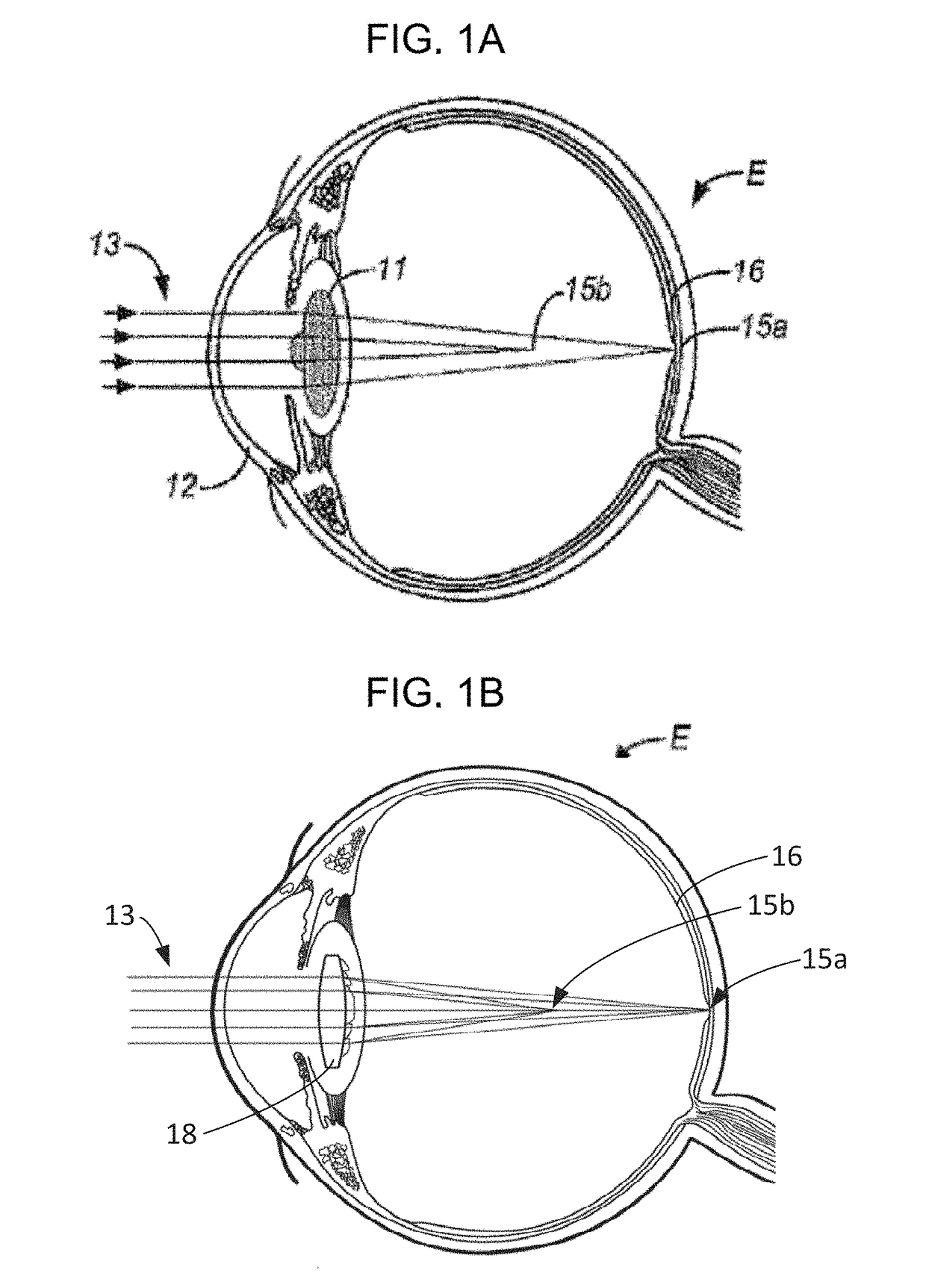
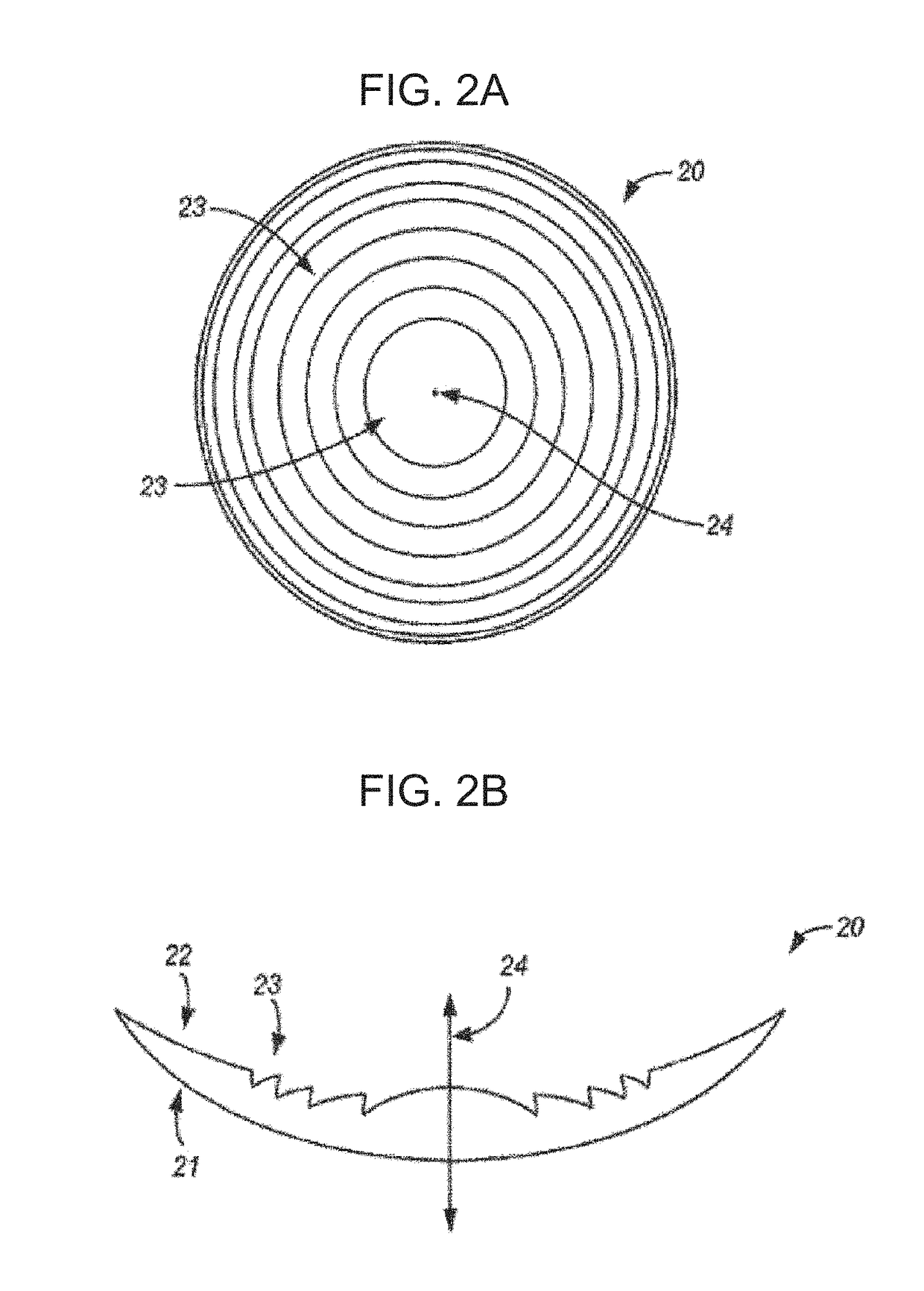
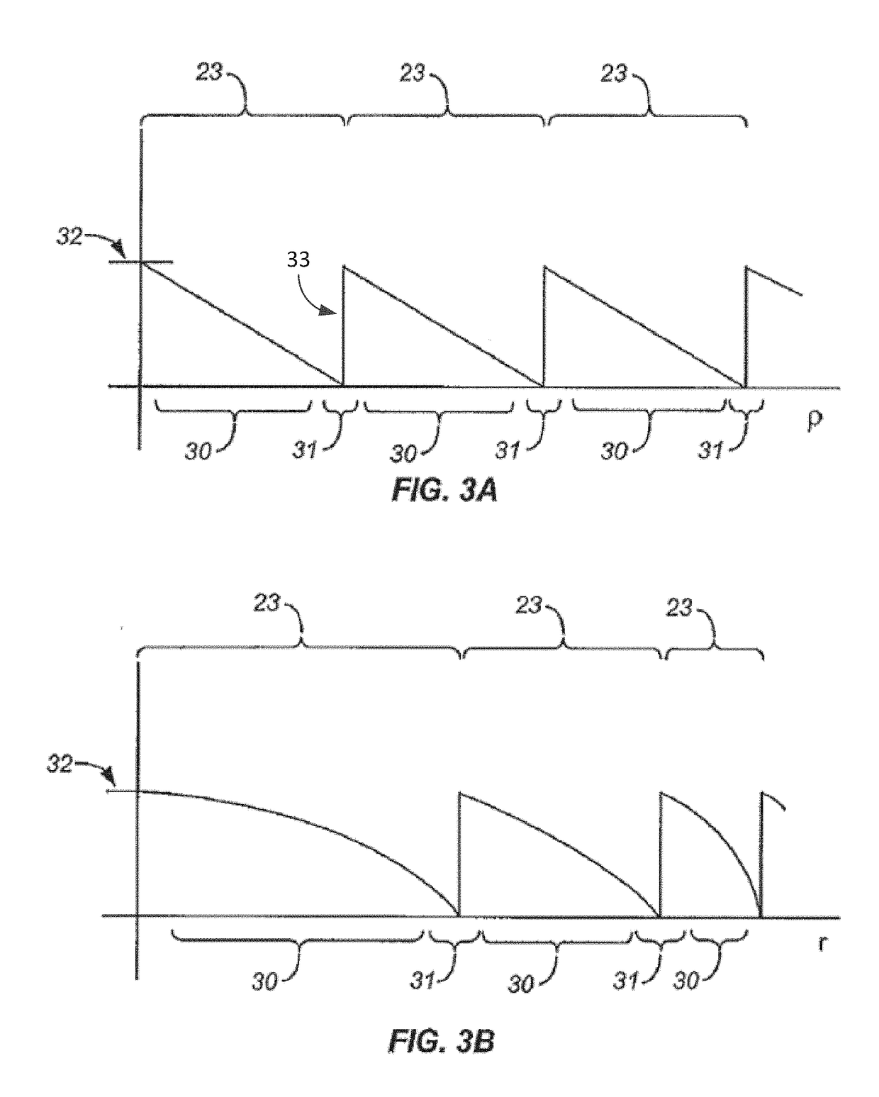
[0030]FIGS. 1A, 1B, 2A, 2B, 3A, and 3B, illustrate multifocal IOL lens geometries, aspects of which are described in U.S. Patent Publication No. 2014-0168602 A1 and U.S. Patent Publication No. 2011-0149236 A1, which are hereby incorporated by reference in their entireties.

[0031]FIG. 1A is a cross-sectional view of an eye E fit with a multifocal IOL 11. As shown, multifocal IOL 11 may, for example, comprise a bifocal IOL. Multifocal IOL 11 receives light from at least a portion of cornea 12 at the front of eye E and is generally centered about the optical axis of eye E. For ease of reference and clarity, FIGS. 1A and 1B do not disclose the refractive properties of other parts of the eye, such as the corneal surfaces. Only the refractive and / or diffractive properties of the multifocal IOL 11 are illustrated.

[0032]Each major face of lens 11, including the anterior (front) surface and posterior (back) surface, generally has a refrac...


PUM


Abstract

Apparatuses, systems and methods for providing improved ophthalmic lenses, particularly intraocular lenses (IOLs), include features for reducing dysphotopsia effects, such as haloes and glare. Exemplary ophthalmic lenses may include a central zone with a first set of two echelettes arranged around the optical axis, the first set having a profile in r-squared space. A middle zone includes a second set of two echelettes arranged around the optical axis, the second set having a profile in r-squared space that is different than the profile of the first set. A peripheral zone includes a third set of two echelettes arranged around the optical axis, the third set having a profile in r-squared space that is different than the profile of the first set and the profile of the second set, the third set being repeated in series on the peripheral zone.

Description

CROSS REFERENCE TO RELATED APPLICATIONS[0001]The present application claims the benefit of U.S. Provisional Application No. 62 / 524,128, filed Jun. 23, 2017, the entire contents of which are incorporated herein by reference.BACKGROUND[0002]Embodiments of the present disclosure relate generally to diffractive ophthalmic lenses, and particular embodiments provide methods, devices, and systems for mitigating or treating vision conditions such as presbyopia, often by determining a desired multifocal power profile and selecting a geometry of the diffractive profile that results in a diffractive lens shape according to the desired power profile and to various parameters of the patient's eye. Embodiments also relate to vision treatment techniques and in particular embodiments, to ophthalmic lenses such as, for example, contact lenses, corneal inlays or onlays, or intraocular lenses (IOLs) including, for example, phakic IOLs and piggyback IOLs (i.e. IOLs implanted in an eye already having an...

Claims


Application Information

Patent Timeline
IPC IPC(8): A61F2/16
CPCA61F2/1627A61F2/1602A61F2/1648A61F2/1618A61F2/164G02C7/041A61F2/145A61F2/1654G02C7/04G02C2202/20A61F2240/001
Inventor ROSEN, ROBERTWEEBER, HENDRIK A.
Owner AMO GRONINGEN
Learn More