Pneumatic elastic band and inflatable system using same

Active Publication Date: 2019-01-03
MICROJET TECH
View PDF0 Cites 2 Cited by
  • Summary
  • Abstract
  • Description
  • Claims
  • Application Information

AI Technical Summary

Benefits of technology

The present invention provides a pneumatic elastic band that can be quickly and safely tightened for easy use. It also provides stability and coverage for the feet. These drawbacks in previous designs are solved by this invention.

Problems solved by technology

However, the shoes with shoelaces have many problems in wearing.
For example, when the shoelaces are loosened while moving, they have to be retied, resulting in inconvenience and waste of time.
In addition, there is also potential danger of wearing shoes with normal shoelaces.
For example, when the shoelaces are accidentally loosened, other people may trip over it, or the shoelaces may be involved in the gap of an escalator, a bicycle chain or a motorcycle pin, which may cause accidents.
When wearing shoe types having normal shoelaces, the degree of looseness and tightness of normal shoelaces is not easy to control.
It takes a longer time to adjust, and it is easy to produce the situation of too tight or too loose, thereby causing the discomfort of the user during wearing.
There are even doubts about occurring dangers.
And when the normal shoelaces are loosened, it is necessary to loosen part of the shoelaces that are penetrated through each shoelace hole so as to allow the user to wear or take off the shoes, in which it often causes time loss and is extremely inconvenient to the user.
Therefore, how to develop a pneumatic elastic band that can solve the drawbacks in prior arts, be rapidly tightened with safety and convenience and can stably cover and fix the feet, is substantially the urgent problem that is needed to be solved right now.

Method used


Image

  • Pneumatic elastic band and inflatable system using same
  • Pneumatic elastic band and inflatable system using same
  • Pneumatic elastic band and inflatable system using same

Examples


Embodiment Construction

[0028]The present disclosure will now be described more specifically with reference to the following embodiments. It is to be noted that the following descriptions of preferred embodiments of this disclosure are presented herein for purpose of illustration and description only. It is not intended to be exhaustive or to be limited to the precise form disclosed.

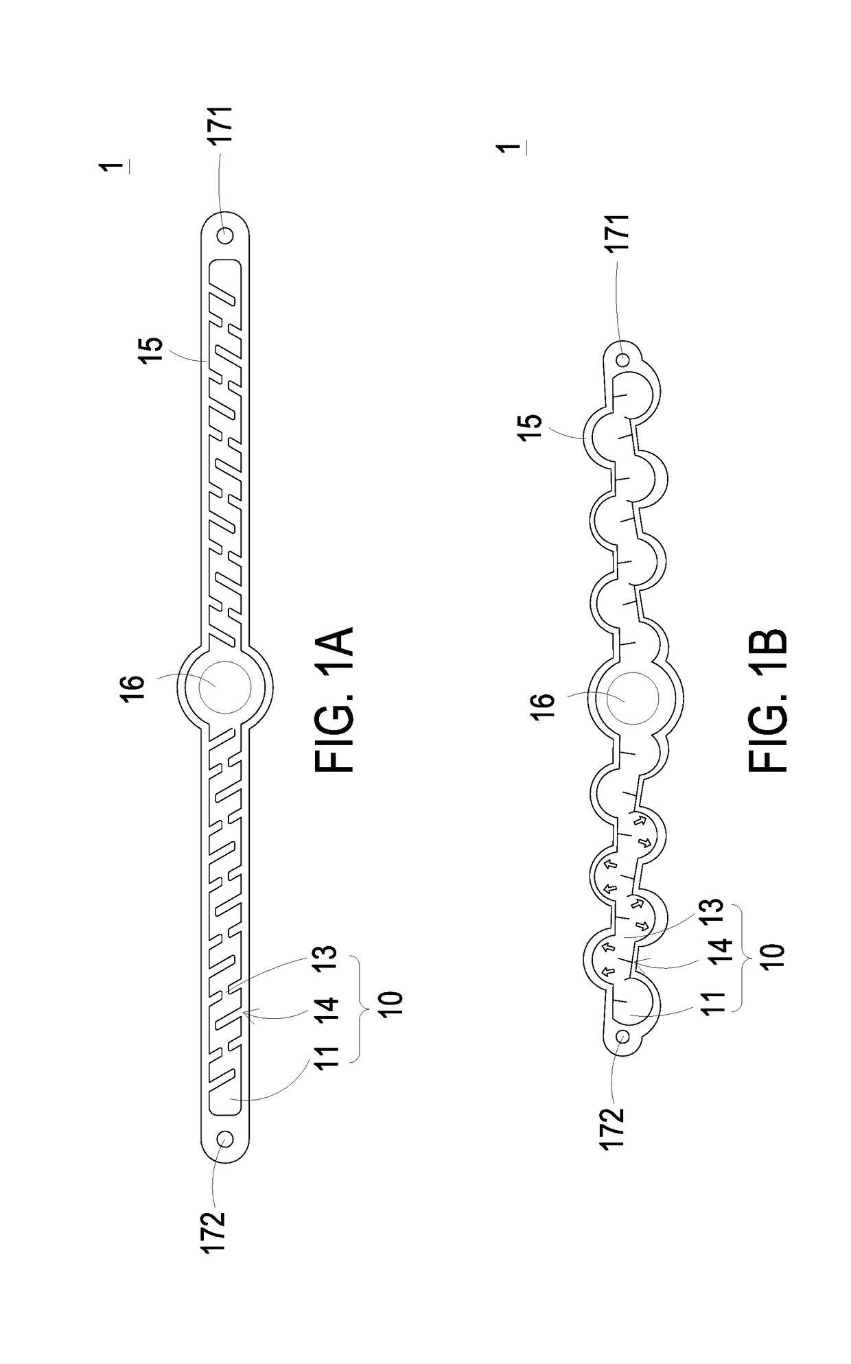
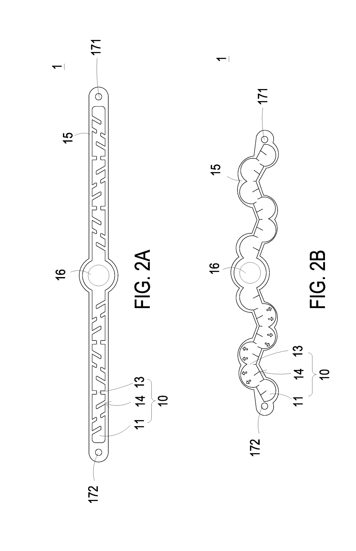
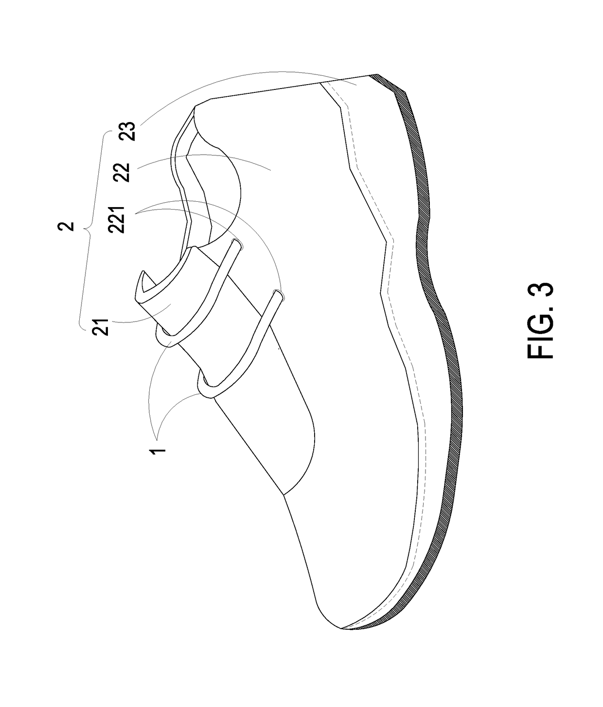
[0029]Please refer to FIGS. 1A and 1B. FIG. 1A is a schematic perspective view illustrating a pneumatic elastic band according to an embodiment of the present disclosure. FIG. 1B schematically illustrates the inflation and expansion of the pneumatic elastic band of FIG. 1A. The pneumatic elastic band of the present disclosure is an elastic band that is inflated or vented to achieve loosening or tightening effect. The pneumatic elastic band can be used in various types of items such as shoelaces of sport shoes, elastic bands of pants, belts, buckle straps of helmets, straps of backpacks, straps of watches, . . . etc., but not li...


PUM


Abstract

A pneumatic elastic band comprises an outer portion, an inflatable portion and a nozzle. The outer portion has a strip-shaped structure with elasticity. The inflatable portion comprises a plurality of expansion portions and a plurality of communication portions. Each of the communication portions is connected between two of the expansion portions adjacent to each other for defining a plurality of gaps. The nozzle is disposed on a surface of the outer portion and communicated with the inflatable portion. When a gas is guided into the inflatable portion through the nozzle, the plurality of expansion portions of the inflatable portion are inflated to fill the gaps and make the inflatable portion contract inwardly, so that the outer portion contracts inwardly and deforms, wherein when the gas is guided out of the inflatable portion, the inflatable portion is deflated and loosened to return to an uninflated state to loosen the shoe.

Description

CROSS-REFERENCE TO RELATED APPLICATION[0001]This application claims priority from Taiwan Patent Application No. 106122228, filed on Jul. 3, 2017, the entire contents of which are incorporated herein by reference for all purposes.FIELD OF THE INVENTION[0002]The present disclosure relates to a pneumatic elastic band and an inflatable system using the same, and more particularly to a pneumatic elastic band which is inflatable, and an inflatable system using such pneumatic elastic band.BACKGROUND OF THE INVENTION[0003]Generally, normal shoelaces are used in most shoes as a means of loosening, tying and fixing the shoes on the feet. However, the shoes with shoelaces have many problems in wearing. For example, when the shoelaces are loosened while moving, they have to be retied, resulting in inconvenience and waste of time. In addition, there is also potential danger of wearing shoes with normal shoelaces. For example, when the shoelaces are accidentally loosened, other people may trip ov...

Claims


Application Information

Patent Timeline
IPC IPC(8): A43C9/00F04B45/027
CPCA43C9/00F04B45/027A43C11/008A43C11/22
Inventor MOU, HAO-JANMO, LI-PANGCHEN, SHIH-CHANGHUANG, CHI-FENGLEE, WEI-MING
Owner MICROJET TECH
Why Eureka
Try Eureka