
Flow control component and shower

Active Publication Date: 2019-01-03
KYLIN SANITARY TECH XIAMEN
View PDF0 Cites 2 Cited by
  • Summary
  • Abstract
  • Description
  • Claims
  • Application Information

AI Technical Summary

Benefits of technology

The invention is a component that can control the water flow of a shower and is convenient for use in hand-held showers.

Problems solved by technology

However, it is relatively inconvenient to regulate the water outflow of the shower through the water mixing switch.
Such flow control mechanism can be operated with a single hand to control the water outflow of the shower, but the structure and manufacturing are both complicated.

Method used


Image

  • Flow control component and shower
  • Flow control component and shower
  • Flow control component and shower

Examples


Embodiment Construction

[0034]The present invention is described in further detail with reference to the attached drawings and embodiment.

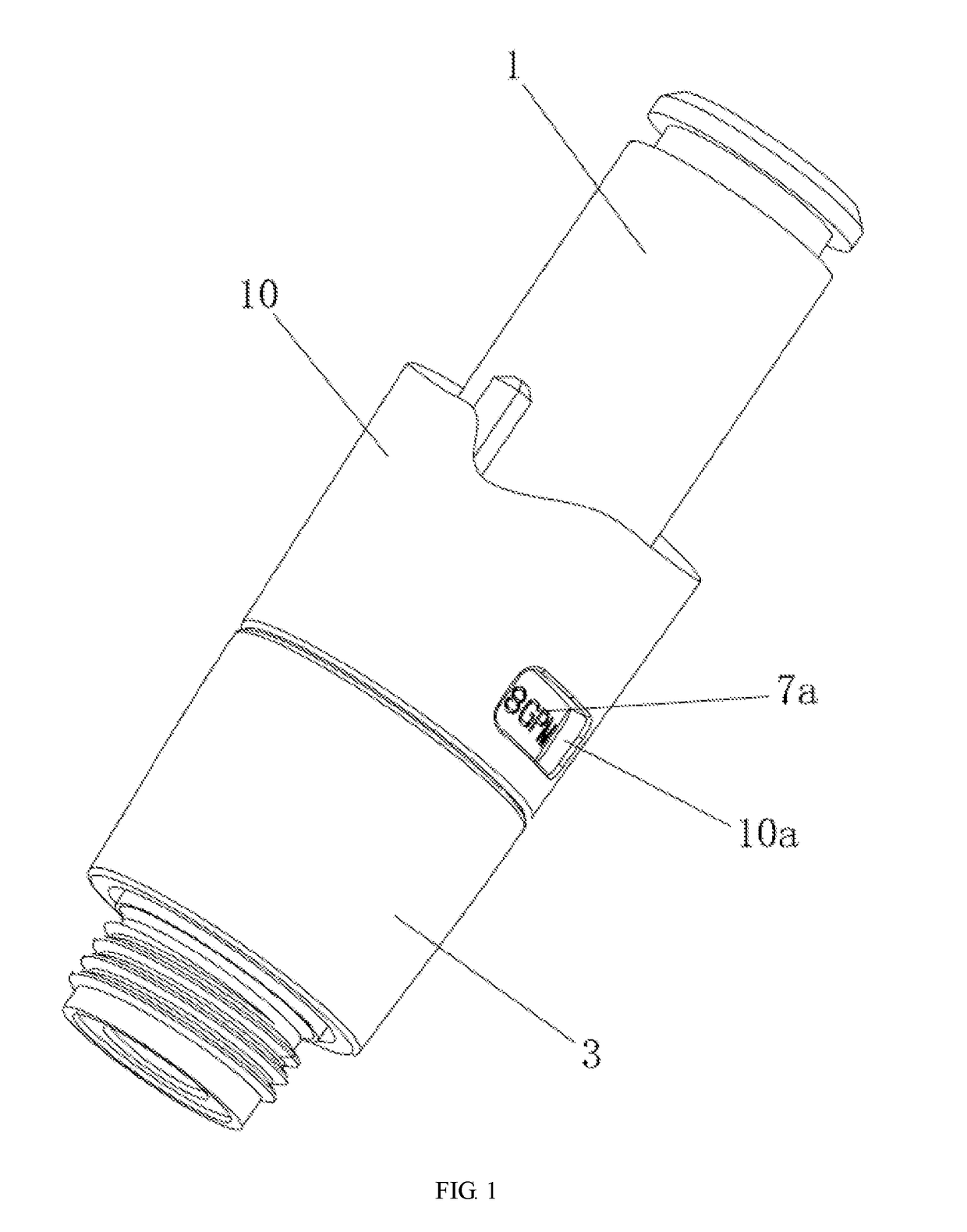
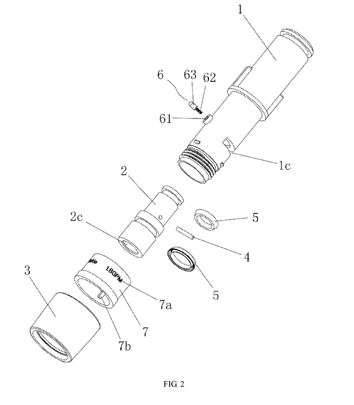
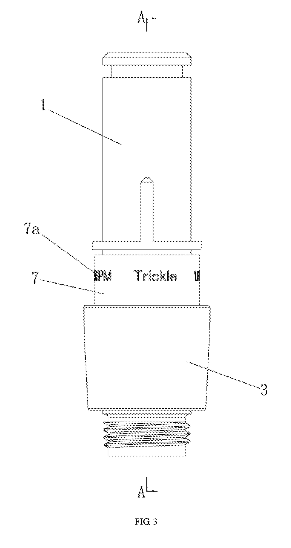
[0035]As shown in FIG. 1-FIG. 7, a flow control component includes a water inlet pipe 1. A partition 1a is disposed in the middle of the water inlet pipe 1; the partition 1a is formed with three water holes 1b which are different in aperture; a first rotating block 2 is installed in an inner hole of the water inlet pipe 1; a first water passage 2a is disposed in the middle of the first rotating block 2; the first rotating block 2 is formed with a water diversion opening 2b on the end face of one end and a main water opening 2c on the end face of the other end; the water diversion opening 2b and the main water opening 2c communicate with each other through a first water passage 2a; the water diversion opening 2b of the first rotating block 2 is eccentrically disposed on the end face of the first rotating block 2, and the water diversion opening 2b of the first rotating bl...


PUM


Abstract

A flow control component comprises a water inlet pipe, and a shower equipped with the flow control component. A partition formed with water holes which are different in aperture is disposed in the middle of the water inlet pipe; a first rotating block with a water diversion opening and a main water opening respectively formed at two ends is installed in an inner hole of the water inlet pipe; a first water passage which communicates with the water diversion opening and the main water opening is disposed in the middle of the first rotating block. The water inlet pipe is externally sleeved with an adjusting sleeve; a toggle pin passes through a radial arc-shaped hole on an outside face of the water inlet pipe; the adjusting sleeves drives the first rotating block to rotate through the toggle pin such that the water diversion opening selectively communicates with the water holes.

Description

BACKGROUND OF THE INVENTIONTechnical Field[0001]The present invention relates to the technical field of the manufacturing of bathroom equipment, in particular a flow control component and a shower.Description of Related Art[0002]In the technical field of the manufacturing of bathroom equipment, common water sprayers such as showers have water outflow usually directly controlled by a water mixing switch. However, it is relatively inconvenient to regulate the water outflow of the shower through the water mixing switch. In order to solve the problem of the relatively inconvenient control of the shower flow, flow control devices which can be directly installed on the showers have been designed, for example, the Chinese patent with a patent number of ZL201521123106.7 and a patent name of “Flow Control Mechanism for Hand-Held Showers” disclosed on Jul. 6, 2016. The flow control mechanism for a hand-held shower adopts the following technical solution: a gripping portion of the hand-held sh...

Claims


Application Information

Patent Timeline
IPC IPC(8): B05B1/18B05B1/30E03C1/04F16K37/00F16K3/26
CPCB05B1/185B05B1/3026E03C2001/026F16K37/0058F16K3/262E03C1/0408F16K11/078F16K31/445F16K37/0008F16K3/085E03C1/0409B05B1/1636B05B1/18F16K3/26F16K3/34
Inventor HUANG, HUILI, QINGSHUANGDENG, XI-JIE
Owner KYLIN SANITARY TECH XIAMEN
Learn More