Separation device for separating particles from a fluid flow

a separation device and fluid flow technology, applied in separation processes, filtration separation, vortex flow apparatus, etc., can solve the problems of increasing pressure loss, requiring not only a relatively large construction volume, and collapse of filter elements

Active Publication Date: 2019-01-10
MCI MANAGEMENT CENT INNSBRUCK INT HOCHSCHULE
View PDF0 Cites 7 Cited by
  • Summary
  • Abstract
  • Description
  • Claims
  • Application Information

AI Technical Summary

Benefits of technology

[0005]It is therefore an object of the present invention to remedy this situation and to provide a separation device for particles from a fluid flow comprising a centrifugal separator, which does not suffer from those drawbacks. In addition, the separation device should have a compact design. In particular, the time until a downstream filter element is covered optionally also with a filter cake should also be as long as possible.

Problems solved by technology

On the contrary, in filter elements with porous media, an adhesion of particles in and on the porous medium itself or on the surface of the filter elements, respectively, occurs with a growing filter cake, accompanied by an increasing pressure loss as far as to a complete collapse of the filter element throughout the filtration period.
Conventional centrifugal separators (cyclone separators) with a single dip tube require not only a relatively large construction volume, but also a post-separation due to the limited separation particle size.
This, in turn, has the disadvantage that the circulation of the fluid in the separation chamber is disturbed in the area of the lower dip tube, resulting in inhomogeneous flows which will put mechanical strain on the centrifugal separator and subsequently will have an adverse effect on the separation.

Method used


Image

  • Separation device for separating particles from a fluid flow
  • Separation device for separating particles from a fluid flow
  • Separation device for separating particles from a fluid flow

Examples


Embodiment Construction

[0035]Based on the figures and the description of the figures, further details and advantages of the invention are explained.

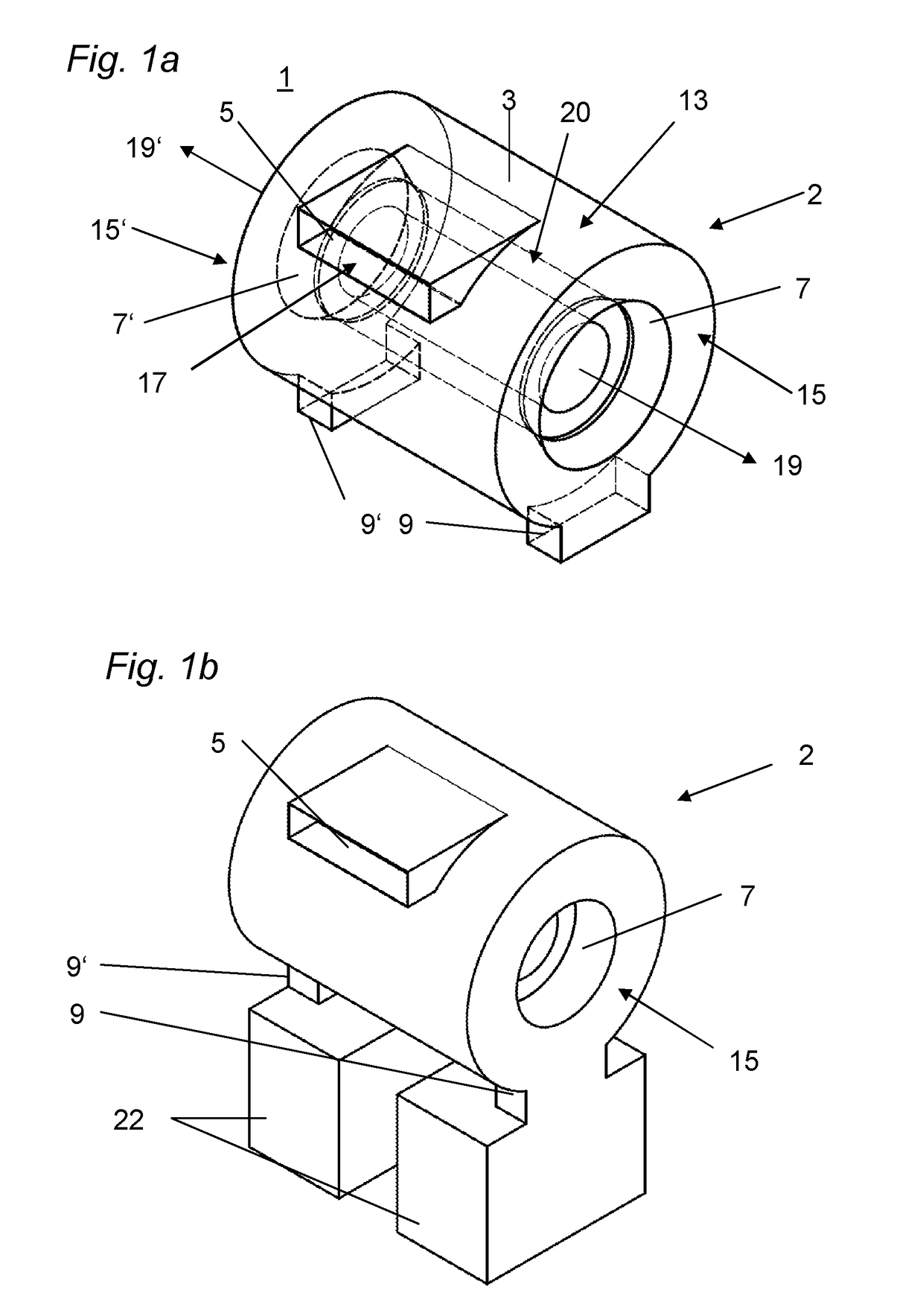
[0036]FIGS. 1a, 1b schematically show perspective illustrations of a separation device for particles from a fluid flow according to an embodiment variant of the invention.

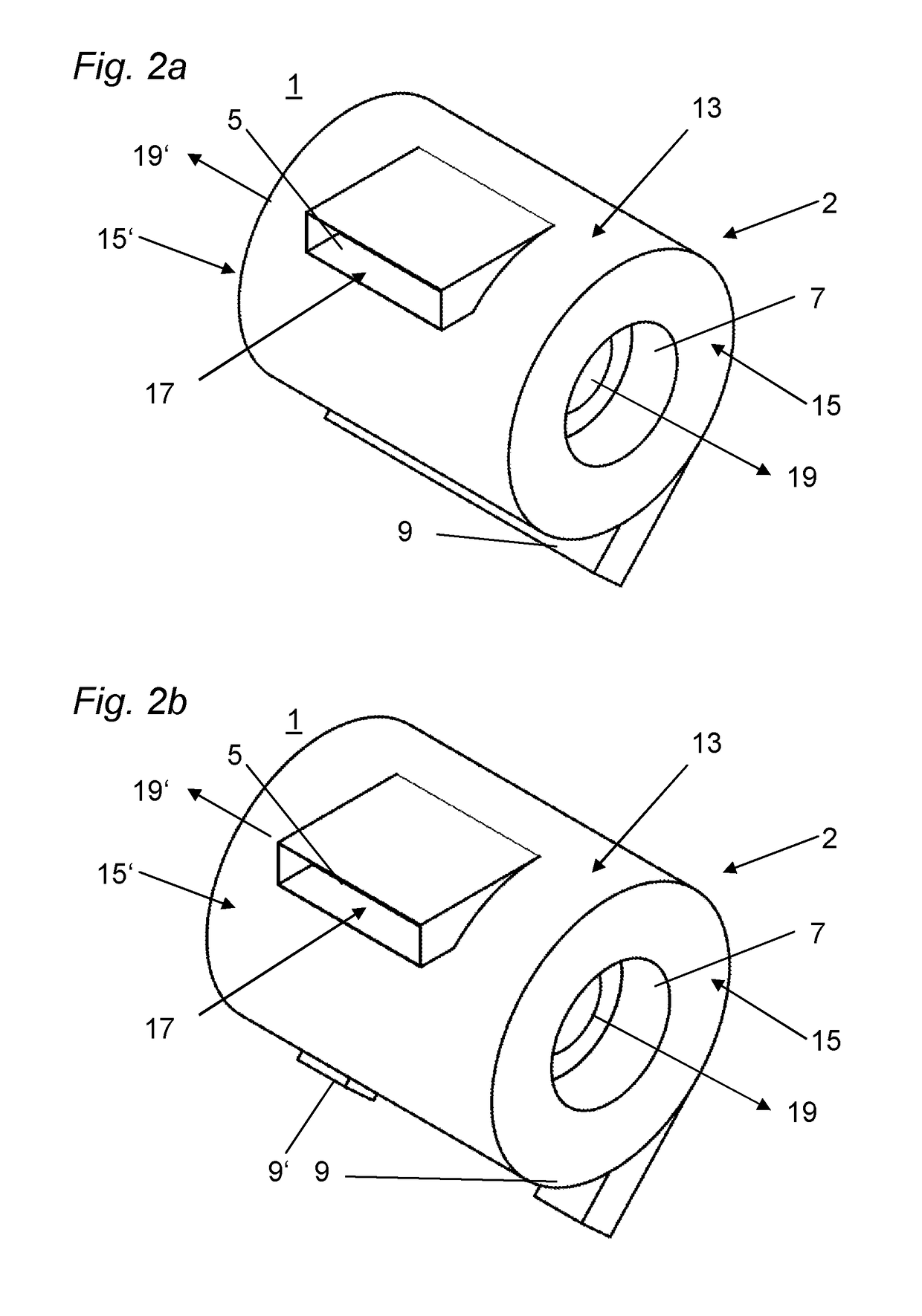
[0037]FIGS. 2a-2c schematically show perspective illustrations of separation devices according to three embodiment variants of the invention with different particle discharge openings.

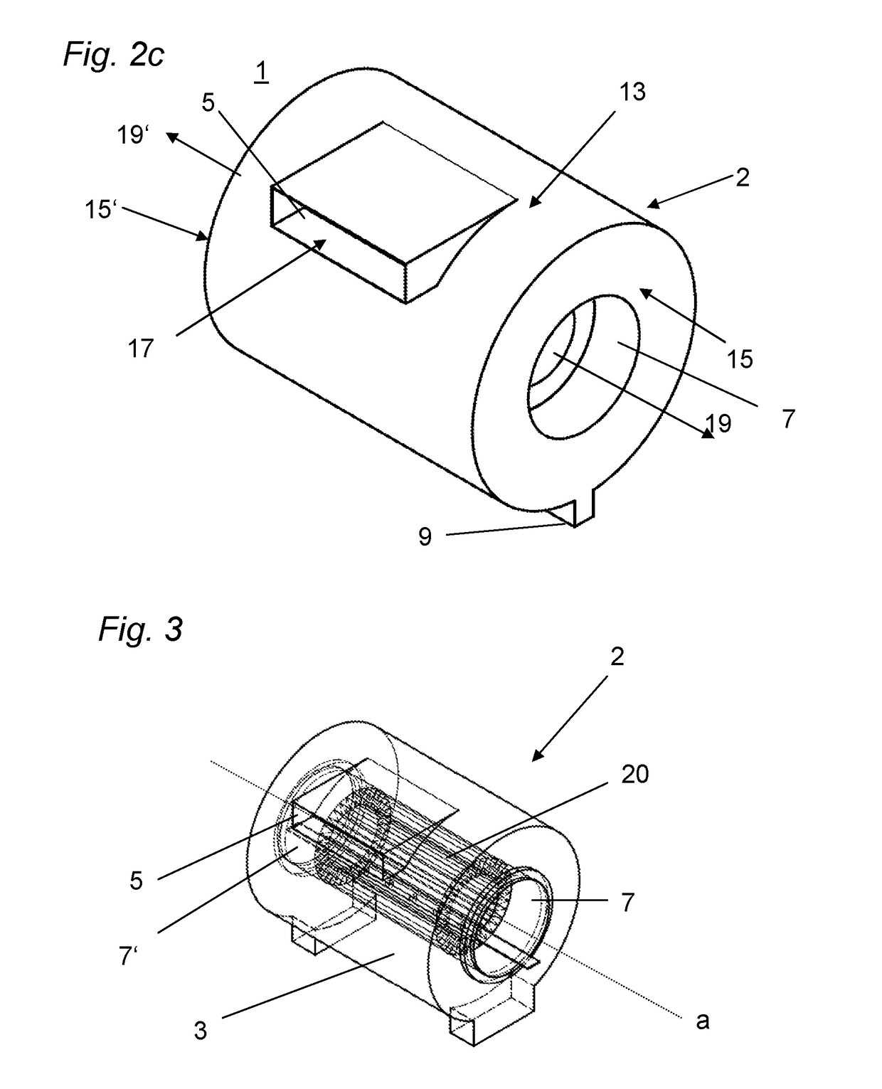
[0038]FIG. 3 shows a separation device with a filter element in the separation chamber.

[0039]FIGS. 4a-4c show embodiment variants of separation devices according to the invention with different shapes for the fluid inlet opening.

[0040]FIGS. 5a, 5b shows two embodiment variants of separation devices with a crude fluid inlet arranged at the bottom.

[0041]FIGS. 6a-6c show views of the embodiment variant of FIG. 1.

[0042]FIGS. 7a-7c show the views according to FIGS. 6a-6c of an alternative embodiment variant and also ...


PUM

PropertyMeasurementUnit
axis of rotationaaaaaaaaaa
shapeaaaaaaaaaa
pressure lossaaaaaaaaaa

Abstract

A separation device (1) for separating particles from a fluid flow, comprising a centrifugal separator (2), wherein the centrifugal separator (2) comprises a separation chamber (3), a fluid inlet (5), at least two dip tubes (7, 7′) and at least one particle discharge opening (9, 9′) and the separation chamber (3) is substantially formed as a rotational body. The rotational body has a casing (13) and two end faces (15, 15′), the fluid inlet (5) opening into the separation chamber (3) tangentially to the surface of the casing (13) and one dip tube (7) being situated in one of the end faces (15) and the other dip tube (7′) being situated in the other end face (15′).

Description

[0001]The invention relates to a separation device for particles from a fluid flow, comprising a centrifugal separator, wherein the centrifugal separator comprises a separation chamber, a fluid inlet, at least one particle discharge opening and at least two dip tubes.PRIOR ART[0002]Separation devices for particles (by which particles or droplets are understood in the following) from a fluid flow find application, for example, in processes for the separation of dispersed solids in fluid flows. In doing so, so-called combination filter elements are very often used, in which various separators are combined. Frequently, a centrifugal separator is used as a pre-separator and combined with a filter element consisting of porous media. The task of the pre-separation is to separate particles from the disperse fluid flow as effectively as possible in order to reduce the burden on the downstream filter element. The combination causes an almost complete separation of the particles, whereby the ...

Claims


Application Information

Patent Timeline
Patent Type & Authority Applications(United States)
IPC IPC(8): B04C3/04B04C3/06B04C9/00B01D46/24B01D46/00B01D45/16B01D50/00
CPCB04C3/04B04C3/06B04C9/00B01D46/24B04C2003/003B01D46/0065B01D45/16B01D50/002B04C2009/004B01D46/0068B04C1/00B04C5/04B04C5/081B04C5/13B04C5/14B01D46/2411B01D46/681B01D46/71B01D50/20B01D35/16
Inventor KRAXNER, MICHAELKOFLER, TOBIAS
Owner MCI MANAGEMENT CENT INNSBRUCK INT HOCHSCHULE
Why Eureka
Try Eureka