
Timepiece oscillator structure with a divisible element

a technology of timepiece and oscillator, applied in the field of timepiece oscillator structure, can solve the problems of high cost, fragile handling of such components, and high cos

Active Publication Date: 2019-01-10
ETA SA MFG HORLOGERE SUISSE
View PDF0 Cites 4 Cited by
  • Summary
  • Abstract
  • Description
  • Claims
  • Application Information

AI Technical Summary

Benefits of technology

The invention helps to make components out of materials that can be easily machined and assembled. This results in safer handling, especially through automated handling methods.

Problems solved by technology

However, handling such components is particularly delicate and any incorrect manoeuvre leads to destruction of components, the cost of which remains still high.

Method used


Image

  • Timepiece oscillator structure with a divisible element
  • Timepiece oscillator structure with a divisible element
  • Timepiece oscillator structure with a divisible element

Examples


Embodiment Construction

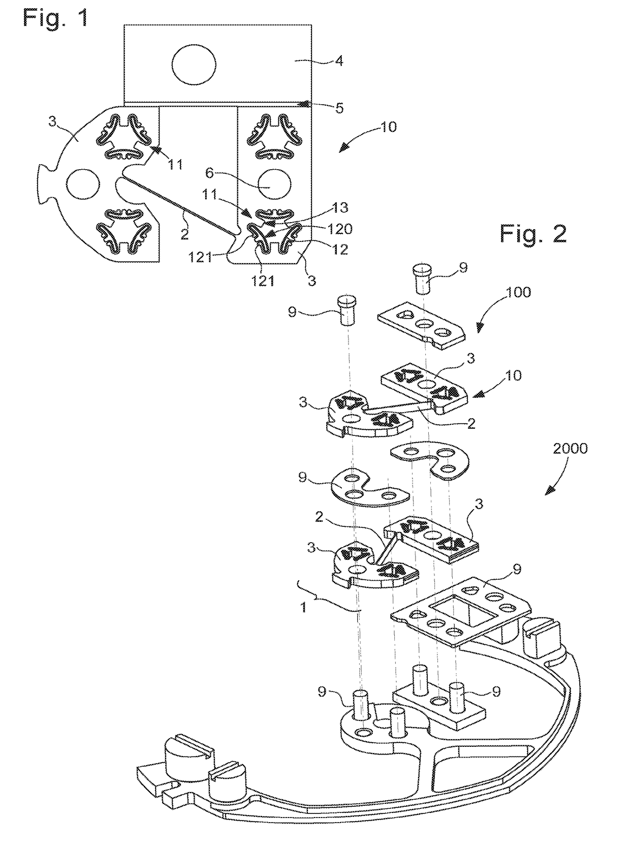
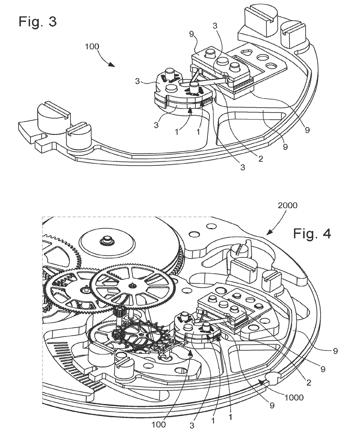
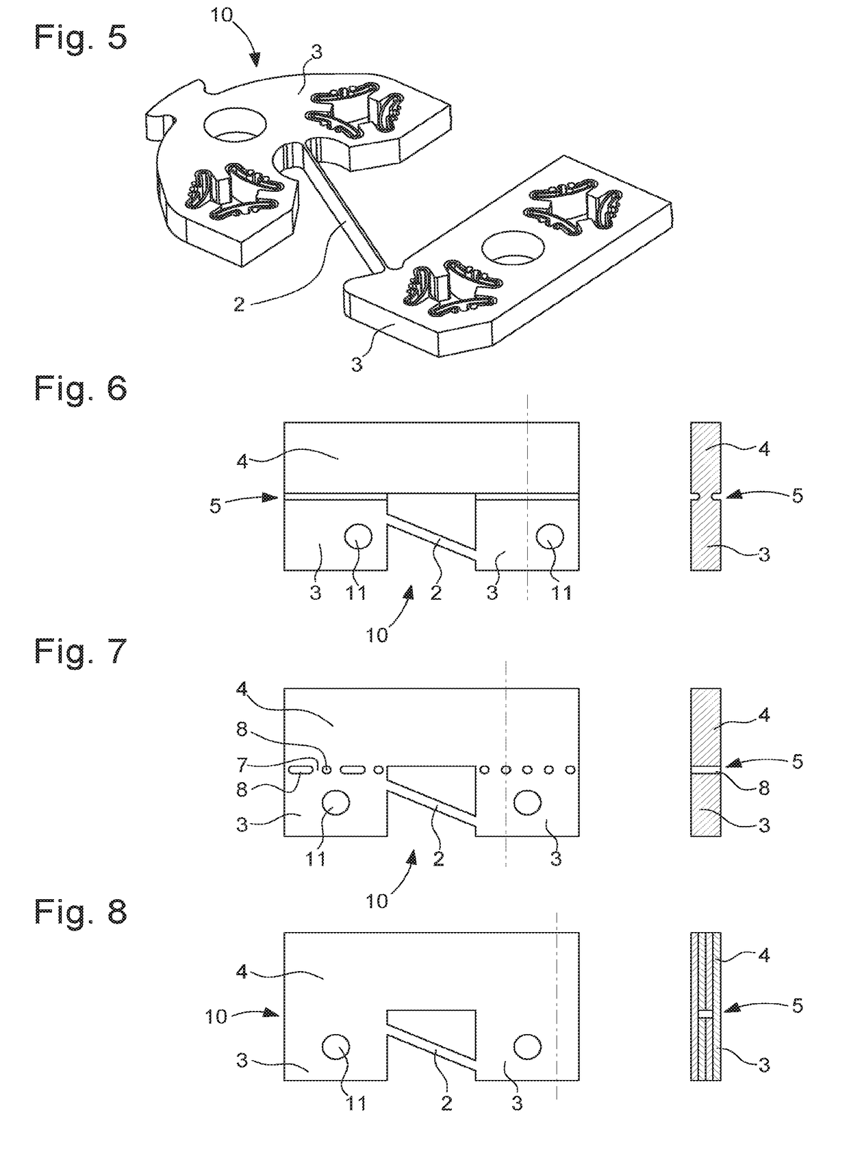
[0034]The invention relates to a timepiece oscillator structure, comprising at least one divisible unit 10.

[0035]This divisible unit 10 is designed to protect, during manufacture, handling, assembly, the most fragile elements of at least one timepiece component 1.

[0036]The divisible unit 10 is designed to be separated, after its assembly with other elements, into one functional part formed by each component 1 which it comprises, and a sacrificial part which has no longer any use within the timepiece mechanism, in the centre of which the component 1 is incorporated. This sacrificial part is designed for easy handling, by an operator or by an automated handling means, and it forms a gripping unit 4 which protects each component 1, and in particular the most fragile elements which the latter encloses, until separation of the gripping unit 4 and components 1 by breaking by bending and / or twisting, cut with a tool such as a wire cutter or saw, or laser-cut, or other.

[0037]The divisible u...


PUM


Abstract

A timepiece oscillator structure includes at least one divisible unit, which includes at least one component which includes at least one flexible blade or at least one blade with necks, joining two main units, each more rigid than the flexible blade or blade with necks, where the divisible unit includes at least one gripping unit adjacent to at least one main unit to which it is connected by at least one divisible linkage which is designed in order to make possible the detachment of this gripping unit from the component when the component is fixed, with at least the particular main unit which is adjacent to the gripping unit, to a more rigid external element than the flexible blade or than the necks of the blade with necks.

Description

[0001]This application claims priority from European patent application No. 17180307.5 filed on Jul. 7, 2017, the entire disclosure of which is hereby incorporated herein by reference.FIELD OF THE INVENTION[0002]The invention relates to a timepiece oscillator structure comprising at least one divisible unit, which comprises at least one component which comprises at least one flexible blade or at least one blade with necks, joining two main units, each more rigid than said flexible blade or blade with necks, where said divisible unit comprises at least one gripping unit which is designed to be adjacent to at least one said main unit to which it is connected by at least one divisible linkage which is designed in order to make possible the detachment of said gripping unit from said component when said component is fixed, by means of at least said particular main unit which is designed to be adjacent to said gripping unit, to a more rigid external element than said flexible blade or tha...

Claims


Application Information

Patent Timeline
Patent Type & Authority Applications(United States)
IPC IPC(8): G04B17/04
CPCG04B17/045G04B17/32G04D3/0035G04B15/14G04B17/06G04B43/002G04B31/02
Inventor MALLET, DANIELCUSIN, PIERRECOURVOISIER, RAPHAELWINKLER, PASCAL
Owner ETA SA MFG HORLOGERE SUISSE
Learn More