Apparatus and method for button-free control of a wearable transcutaneous electrical nerve stimulator using interactive gestures and other means

Active Publication Date: 2019-01-24
NEUROMETRIX
View PDF0 Cites 3 Cited by
  • Summary
  • Abstract
  • Description
  • Claims
  • Application Information

AI Technical Summary

Benefits of technology

The present invention provides a novel TENS device without the need for mechanical actuators, such as push-buttons or switches. Instead, the device is controlled through intentional gestures and other means, such as a three-axis accelerometer or wireless connections. The device can automatically transition between a standby mode and an active mode based on the detected motion and orientation of the device. The device can also monitor the impedance between a pair of electrodes and the body of the user to determine the on-skin status of the electrodes. The controller can automatically initiate therapy based on the detected motion or the on-skin status. The invention provides a more convenient and efficient way to control TENS therapy.

Problems solved by technology

Intensities below the threshold of sensation are not clinically effective.
Furthermore, it is difficult to locate and actuate a push-button under clothing unless the push-button is large.
However, a large push-button increases the size, thickness, and manufacturing complexity of the device, thereby decreasing the wearability of the device.
Moreover, push-buttons and other mechanical actuators are prone to accidental activation such as when the user is sleeping.
Maintaining a continuous active communication link between the TENS device and the smartphone App can be expensive in terms of battery power consumption, leading to the need for frequent recharges and user inconvenience.
Volume requirements put an upper limit on the physical size of a rechargeable battery contained within the TENS device.
The capacity of the battery powering the TENS device, which is typically somewhat proportional to the size of the battery, is thus limited in such wearable TENS devices.

Method used


Image

  • Apparatus and method for button-free control of a wearable transcutaneous electrical nerve stimulator using interactive gestures and other means
  • Apparatus and method for button-free control of a wearable transcutaneous electrical nerve stimulator using interactive gestures and other means
  • Apparatus and method for button-free control of a wearable transcutaneous electrical nerve stimulator using interactive gestures and other means

Examples


Embodiment Construction

The TENS Device in General

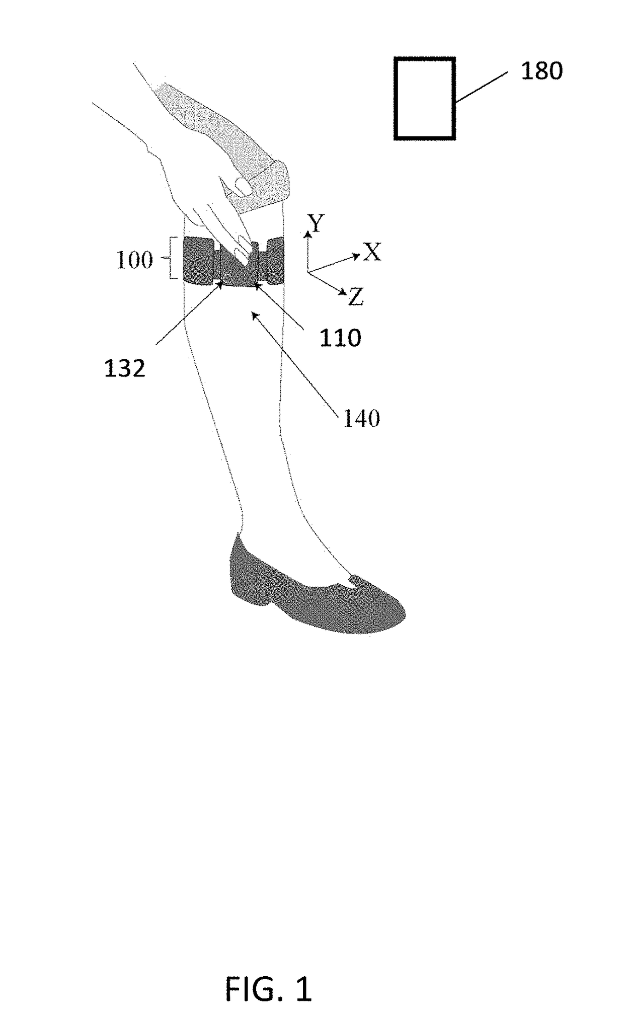
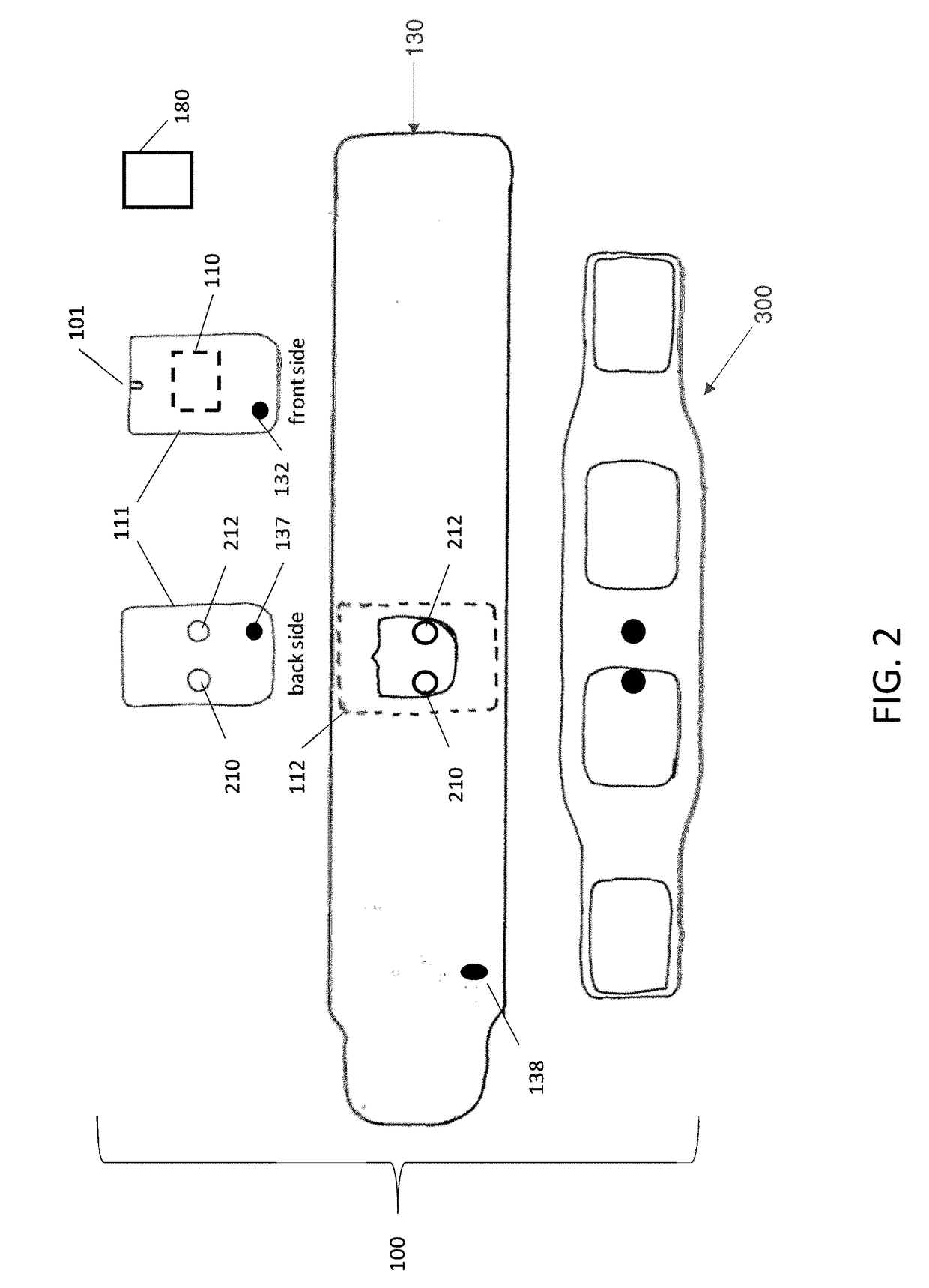
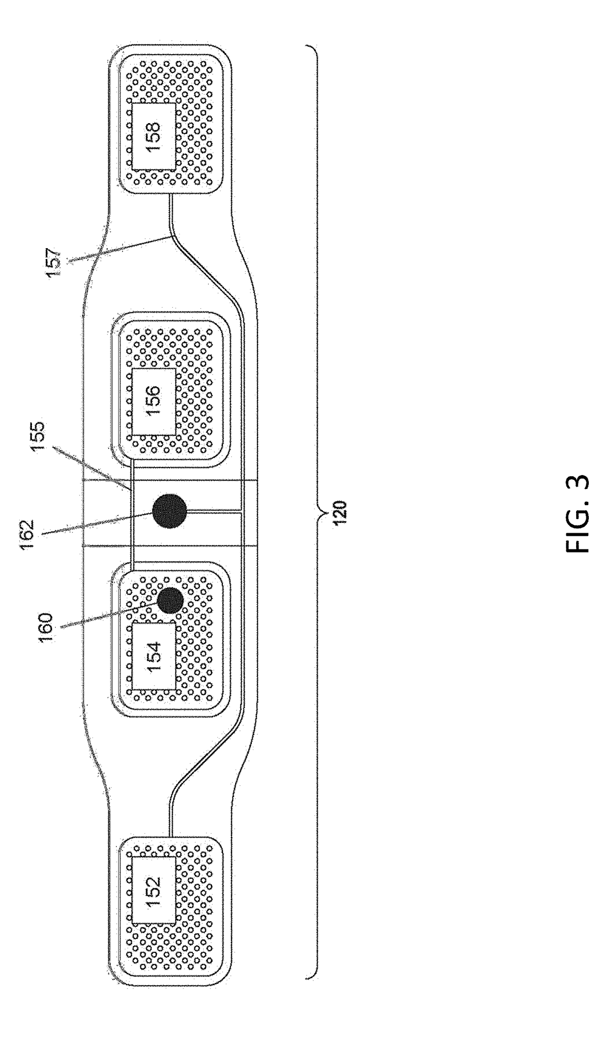
[0102]The present invention comprises the provision and use of a novel TENS device with a stimulator designed to be placed on a user's upper calf (or other anatomical location) and a pre-configured electrode array designed to provide electrical stimulation to at least one nerve disposed in the user's upper calf (or other anatomical location). A key feature of the present invention is that the novel TENS device contains no mechanical actuators (e.g., push-buttons, switches, dials, etc.) for controlling operation of the TENS device.

[0103]More particularly, and looking now at FIG. 1, there is shown a novel TENS device 100 formed in accordance with the present invention, with novel TENS device 100 being shown worn on a user's upper calf 140. A user may wear TENS device 100 on one leg or on both legs (either one at a time or simultaneously), or a user may wear a TENS device 100 on another area of the body separate from, or in addition to, a TENS device 100 worn ...


PUM


Abstract

Apparatus for transcutaneous electrical nerve stimulation in a user, the apparatus comprising: a stimulator for electrically stimulating at least one nerve; a stimulator housing; a monitor for monitoring transient motion of the stimulator housing; an analyzer for analyzing transient motion monitored by the monitor for determining whether transient motion of the stimulator housing has occurred; and a controller for automatically transitioning at least one of the stimulator, the monitor, and the analyzer between a standby mode and a power save mode; wherein the power save mode supports a subset of the functionality of the stimulator and the monitor which is available in the standby mode so as to conserve battery power in the power save mode.

Description

REFERENCE TO PENDING PRIOR PATENT APPLICATIONS[0001]This patent application:[0002](1) is a continuation-in-part of pending prior U.S. patent application Ser. No. 15 / 824,351, filed Nov. 28, 2017 by Neurometrix, Inc. and Thomas Ferree et al. for TRANSCUTANEOUS ELECTRICAL NERVE STIMULATOR WITH USER GESTURE DETECTOR AND ELECTRODE-SKIN CONTACT DETECTOR, WITH TRANSIENT MOTION DETECTOR FOR INCREASING THE ACCURACY OF THE SAME (Attorney's Docket No. NEURO-6667 CON), which patent application is a continuation of prior U.S. patent application Ser. No. 14 / 269,887, filed May 5, 2014 by Neurometrix, Inc. and Thomas Ferree et al. for TRANSCUTANEOUS ELECTRICAL NERVE STIMULATOR WITH USER GESTURE DETECTOR AND ELECTRODE-SKIN CONTACT DETECTOR, WITH TRANSIENT MOTION DETECTOR FOR INCREASING THE ACCURACY OF THE SAME (Attorney's Docket No. NEURO-6667), which in turn:[0003](i) is a continuation-in-part of prior U.S. patent application Ser. No. 14 / 230,648, filed Mar. 31, 2014 by NeuroMetrix, Inc. and Shai Go...

Claims


Application Information

Patent Timeline
IPC IPC(8): A61N1/36G06F3/01A61N1/08A61B5/11A61N1/04
CPCG06F3/015A61N1/0456A61N2001/083A61B2562/0219A61N1/36021G06F3/017A61N1/08A61N1/0492A61B5/11A61B2560/0276A61N1/36031A61B5/6828A61B5/7455A61B5/7475A61B5/1118A61B5/1123A61B5/681G06F3/0346G06F1/3231Y02D10/00G06F2200/1636G06F1/163
Inventor GOZANI, SHAI N.KONG, XUANFERREE, THOMAS C.
Owner NEUROMETRIX
Why Eureka
Try Eureka