Printing method

Inactive Publication Date: 2019-01-24
FUJIFILM CORP
View PDF3 Cites 5 Cited by
  • Summary
  • Abstract
  • Description
  • Claims
  • Application Information

AI Technical Summary

Benefits of technology

The present invention solves problems in printing by providing a method that allows for the creation of high-definition patterns, while also increasing productivity.

Problems solved by technology

In JP2013-241013A, since the portion which has not been coated with the ink is covered with a gating agent using an ink jet, high-accuracy patterning cannot be performed.
Therefore, a high-definition pattern cannot be obtained.
Accordingly, high-definition pattern cannot be obtained, and thus a high-definition ink image cannot be obtained.
In JP2002-137528A, high productivity is difficult to be realized because stencil needs to be prepared according to the pattern.

Method used


Image

  • Printing method
  • Printing method
  • Printing method

Examples


Embodiment Construction

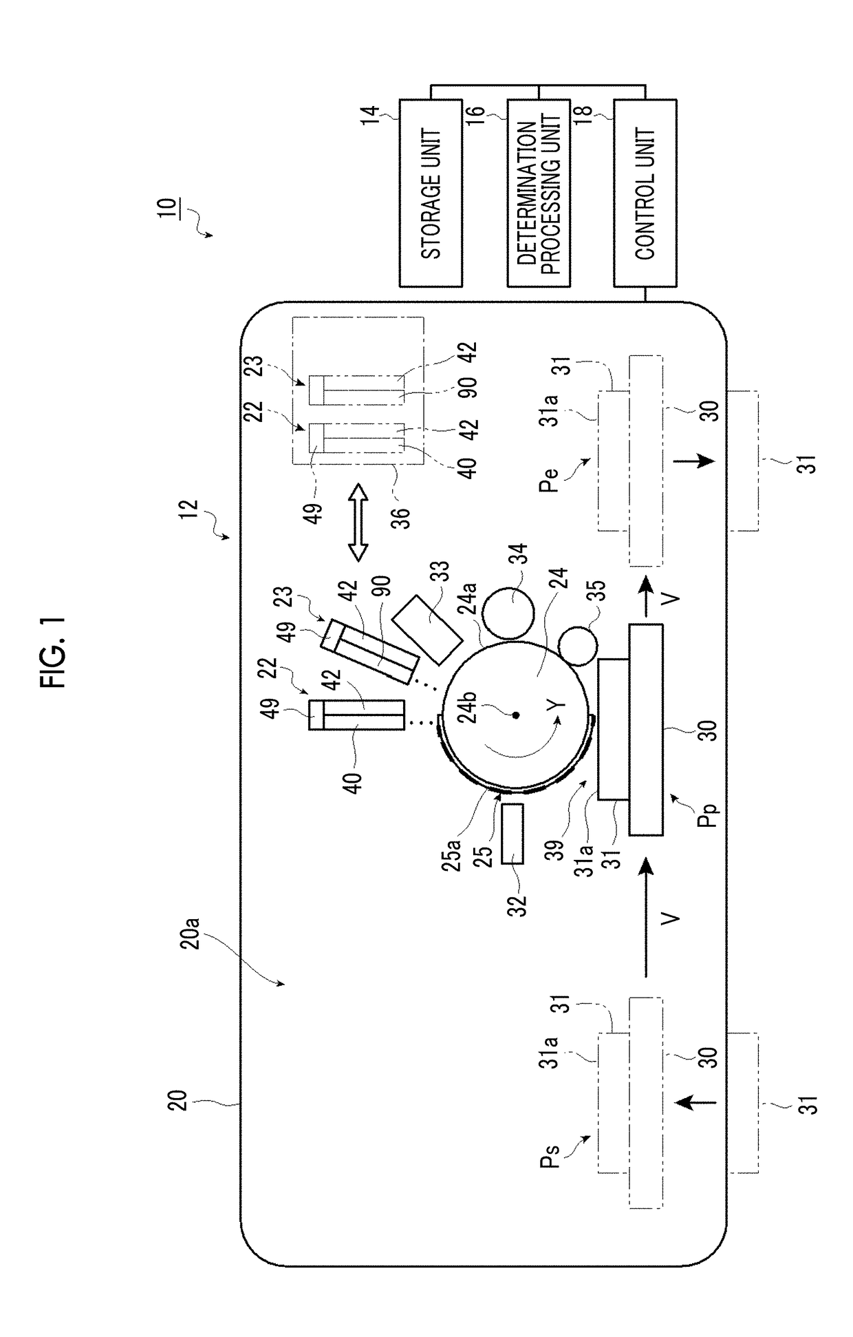
[0058]Hereinafter, a printing method of the present invention will be described in detail based on preferred embodiments illustrated in the accompanying drawings. The present invention is not limited to the embodiments of the printing device and the printing method described below.

[0059]Further, the numerical ranges shown using “to” indicate ranges including the numerical values described before and after “to”. For example, the expression “ε is in a range of a numerical value β1 to a numerical value β2” means that the range of c includes the numerical value β1 and the numerical value β2 and is represented by “β1≤ε≤β2” using a mathematical symbol.

[0060]Further, for example, an angle of “parallel”, “vertical”, or “orthogonal” means that a difference between this angle and the exact angle is less than 5 degrees unless otherwise specified. The difference between this angle and the exact angle is preferably less than 4 degrees and more preferably less than 3 degrees. Further, the “same” ...


PUM

PropertyMeasurementUnit
Diameteraaaaaaaaaa

Abstract

Provided is a printing method which enables formation of a high-definition printing pattern with high productivity. The printing method includes a treatment liquid application step of applying a treatment liquid, in a treatment liquid set pattern, to a pattern formation region of a printing plate in the printing plate on which a pattern has been formed; an ink application step of applying an ink, in an ink set pattern, to the pattern formation region of the printing plate to which the treatment liquid has been applied; and a transfer step of transferring the ink applied to the pattern formation region of the printing plate to a substrate. The treatment liquid is used for increasing a second diameter of the ink after application of the treatment liquid compared to a first diameter of the ink landed on the pattern formation region without application of the treatment liquid.

Description

CROSS-REFERENCE TO RELATED APPLICATIONS[0001]This application is a Continuation of PCT International Application No. PCT / JP2017 / 012953 filed on Mar. 29, 2017, which claims priority under 35 U.S.C. § 119(a) to Japanese Patent Application No. 2016-068194 filed on Mar. 30, 2016. The above application is hereby expressly incorporated by reference, in its entirety, into the present application.BACKGROUND OF THE INVENTION1. Field of the Invention[0002]The present invention relates to a printing method of applying a treatment liquid to a pattern formation region of a printing plate in a treatment liquid set pattern and particularly relates to a printing method of forming a high-definition printing pattern with high productivity.2. Description of the Related Art[0003]Currently, printing is used not only for forming characters and photos but also for forming a patterned wiring and a wiring board.[0004]JP2013-241013A describes a printing method of patterning a gating agent on a plate having a...

Claims


Application Information

Patent Timeline
IPC IPC(8): B41F3/81B41F31/08B41J2/01B41J2/005B41J11/00B41M1/10H05K3/12
CPCB41F3/81B41F31/08B41J2/01B41J2/0057B41J11/0015B41M1/10H05K3/12B41F31/28B41J2/2114B41J2/2146B41J2025/008B41M5/0011B41M5/0256
Inventor ITOH, MITSUHISAKODAMA, KENICHI
Owner FUJIFILM CORP
Why Eureka
Try Eureka