Air flow deflector assembly for a thrust reverser system for reducing re-ingestion of reverse efflux air flow and method for the same

a technology of air flow deflector and reverser, which is applied in the direction of aircraft power plant components, machines/engines, transportation and packaging, etc., can solve the problems of engine fan damage, engine fan blade damage, engine damage, etc., and achieve the effect of reducing the re-ingestion of reverse efflux air flow

Active Publication Date: 2019-01-24
THE BOEING CO
View PDF6 Cites 4 Cited by
  • Summary
  • Abstract
  • Description
  • Claims
  • Application Information

AI Technical Summary

Benefits of technology

[0015]When the air flow deflector apparatus is in the deployed thrust reversing position, upon landing of the air vehicle, the air flow deflector apparatus deflects the reverse efflux air flow in an outward direction away from the at least one engine, to produce a deflected reverse efflux air flow. This thereby reduces re-ingestion of the revers

Problems solved by technology

At such lower landing speed, reverser efflux air flow may pose a potential re-ingestion risk, if it is re-ingested at an air flow inlet of the engine.
Prolonged re-ingestion of reverser efflux air flow at the air flow inlet of the engine may cause damage to the engine fan, the engine fan blades, and/or other internal engine parts, due to the increasing temperature of the re-ingested reverser efflux air flow, as it continuously re-circulates in and out of the engine.
Such damage to the engine fan

Method used


Image

  • Air flow deflector assembly for a thrust reverser system for reducing re-ingestion of reverse efflux air flow and method for the same
  • Air flow deflector assembly for a thrust reverser system for reducing re-ingestion of reverse efflux air flow and method for the same
  • Air flow deflector assembly for a thrust reverser system for reducing re-ingestion of reverse efflux air flow and method for the same

Examples


Embodiment Construction

[0038]Disclosed examples will now be described more fully hereinafter with reference to the accompanying drawings, in which some, but not all of the disclosed examples are shown. Indeed, several different examples may be provided and should not be construed as limited to the examples set forth herein. Rather, these examples are provided so that this disclosure will be thorough and complete and will fully convey the scope of the disclosure to those skilled in the art.

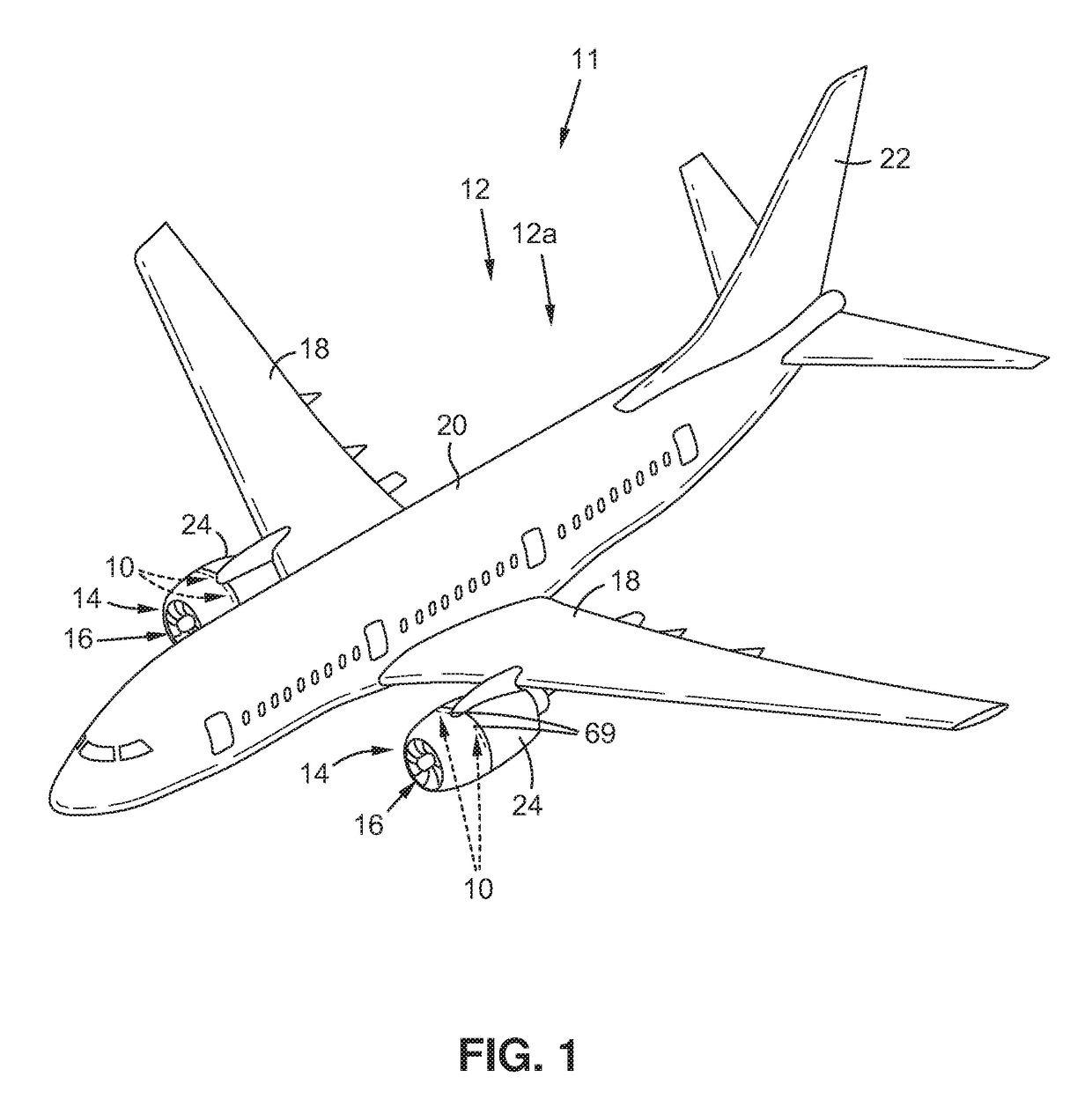
[0039]Now referring to the Figures, FIG. 1 is an illustration of a perspective view of a vehicle 11, such as an air vehicle 12, for example, an aircraft 12a, that may incorporate a disclosed example of an air flow deflector assembly 10 for a thrust reverser system 24. As shown in FIG. 1, the vehicle 11, such as the air vehicle 12, for example, the aircraft 12a, comprises two nacelles 14 which shroud or surround two engines 16, respectively, for example, two gas turbine engines. The vehicle 11, such as the air vehicle 12 ...


PUM


Abstract

There is provided an air flow deflector apparatus for a thrust reverser system of an engine of an air vehicle. The air flow deflector apparatus is movable between a stowed non-reversing position and a deployed thrust reversing position, to deflect an air flow out of the engine, and to provide an effective reverse thrust for the thrust reverser system. There is further provided an air flow deflector assembly for a structure. The air flow deflector assembly has the air flow deflector apparatus, an extender member, and a recessed housing disposed in the structure. The air flow deflector assembly has an air flow deflector actuator that moves the air flow deflector apparatus between a stowed position and a deployed position adjacent to a reverse efflux air flow exit portion of the structure. The air flow deflector assembly deflects a reverse efflux air flow away from being re-ingested into the structure.

Description

BACKGROUND1) Field of the Disclosure[0001]The disclosure relates generally to thrust reverser systems and methods for engines used on aircraft, and more particularly, to air flow deflector assemblies for thrust reverser systems and methods for gas turbine engines used on aircraft, to reduce re-ingestion of reverse efflux air flow by the engines.2) Description of Related Art[0002]Vehicles, such as commercial and military jet aircraft, use thrust reversers on the aircraft's jet engines, such as gas turbine engines, to block forward thrust or redirect the forward thrust into a reverse thrust, in order to reduce the aircraft's speed just after landing, to reduce wear on the aircraft's brakes, and to enable shorter landing distances. An aircraft thrust reverser is typically deployed, after landing, at a high landing speed, e.g., approximately 115-120 knots, and is typically stowed or retracted, after landing, at a low landing speed, e.g., approximately 50-60 knots. At such lower landing ...

Claims


Application Information

Patent Timeline
IPC IPC(8): F02K1/72B64D29/06B64D27/18F02K1/76
CPCF02K1/72B64D29/06F05D2240/14F02K1/763F05D2220/323B64D27/18Y02T50/60
Inventor CHUCK, CHENKIM, SUK C.
Owner THE BOEING CO
Why Eureka
Try Eureka