
Lubricated seal with axial lip

a technology of axial lip and lubricating seal, which is applied in the direction of mechanical equipment, engine components, transportation and packaging, etc., can solve the problems of inability to provide an adequate thickness of oil film to adequately separate the sealing contact, prolong and increase the amount of grease. , the effect of prolonging the life of the seal

Inactive Publication Date: 2019-01-24
AB SKF
View PDF0 Cites 3 Cited by
  • Summary
  • Abstract
  • Description
  • Claims
  • Application Information

AI Technical Summary

Benefits of technology

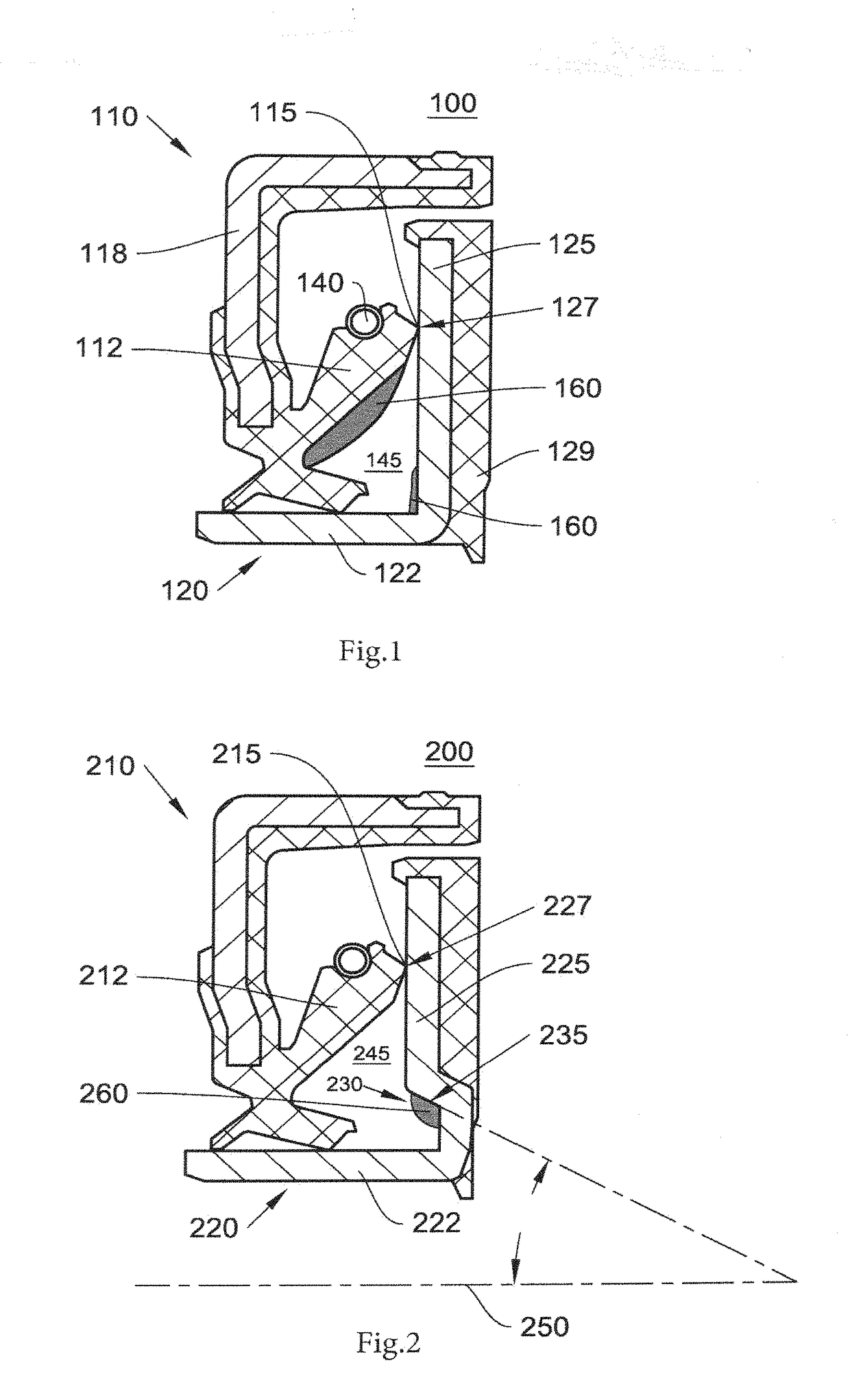
[0007]In grease lubricated seals, the lubrication condition, or film thickness, is assumed to be determined by the availability of lubricant near the sealing contact. The present inventor has found that the available lubricant predominantly stems from grease that is present on a rotating part of the seal. Over time, the grease on the rotating part loses its base oil and eventually becomes incapable of providing an oil film thickness that adequately separates the sealing contact. The time at which this inadequate film thickness occurs can therefore be extended by increasing the amount of grease on the rotating part of the seal.
[0008]Thus, the present invention resides in a rotary seal comprising a first part having an axial sealing lip and a second part having an axial counterface against which the axial sealing lip bears, whereby one of the first and second parts is rotational with respect to the other of the first and second parts. According to the invention, the rotational part is provided with a reservoir for retaining a volume of grease at a location radially inward of the axial sealing lip. The reservoir is designed such that the movement of grease under the action of centrifugal force is prevented, while the movement of base oil, which bleeds from the volume of grease retained in the reservoir, is allowed. As a result, the supply of base oil to the sealing contact takes place for a longer period of time, which extends the life of the seal.
[0013]A seal according to the invention is provided with a grease lubricant. The grease may be provided in a cavity of the seal, in an amount greater than the volume of grease retained in the reservoir. In an advantageous development, the reservoir is specifically filled with grease, such that the retained volume of grease represents at least 80% of the total volume of grease in the seal. Since the grease in the reservoir is the main source of base oil for lubricating the sealing contact, the amount of grease used can be significantly reduced while, at the same time, seal life is extended.

Problems solved by technology

Over time, the grease on the rotating part loses its base oil and eventually becomes incapable of providing an oil film thickness that adequately separates the sealing contact.
As a result, the supply of base oil to the sealing contact takes place for a longer period of time, which extends the life of the seal.
As a result, an axial component of the centrifugal force acting on the volume of grease is insufficient to cause sideways movement of the grease, but is sufficient to allow side-flow of base oil.

Method used


Image

  • Lubricated seal with axial lip
  • Lubricated seal with axial lip
  • Lubricated seal with axial lip

Examples


first embodiment

[0028]An example of a seal according to the invention is shown in FIG. 2. The seal 200 is suitable for use in a wheel bearing unit adapted for inner ring rotation as described above. The seal comprises a first part 210 having an elastomeric element 212 with an axial sealing lip 215, whereby the first part 210 is identical to the first part of the seal shown in FIG. 1. The second part 220 of the seal is formed by a slinger which has a radial flange part 225 and a cylindrical part 222. A sealing contact is defined between the axial sealing lip 215 and an axial counterface 227 on the radial flange part, and the slinger rotates about a rotational axis 250. According to the invention, the slinger is provided with a reservoir 230 for retaining a volume of grease 260 at a location radially inward of the sealing contact. In this example, the reservoir 230 is formed by a bend in the flange part 225 of the slinger, such that the flange part further comprises an axially extending surface 235. ...

second embodiment

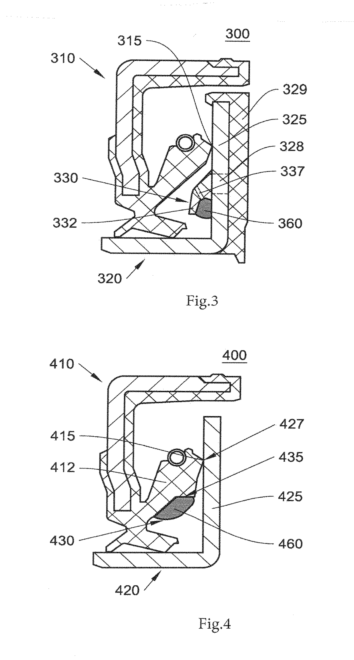
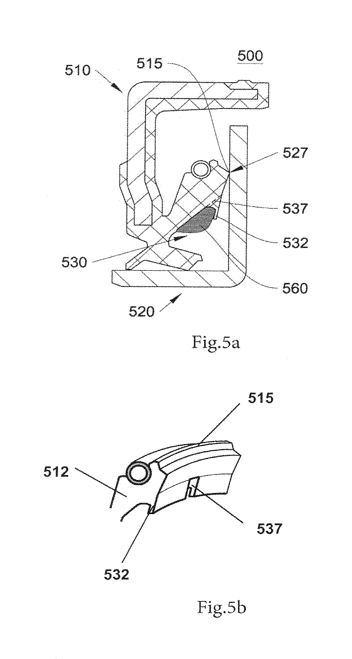
[0033]In the examples discussed thus far, the second part of the seal (the part comprising the axial counterface) has formed the rotating part of the seal. In a second embodiment, the first part of the seal forms the rotational part. A first example of such a seal according to the invention is shown in FIG. 4.

[0034]The second part of the seal 400 is again formed by a slinger 420, which has an axially oriented counterface 427 on the flange part 425. The first part 410 of the seal comprises a metal casing element to which an elastomeric element 412 is bonded. The elastomeric element has an axial sealing lip 415, which is in sealing contact with the counterface 427. Further, the elastomeric element 412 comprises a reservoir 430 according to the invention, which retains a volume of grease 460 at a location radially inward of the sealing contact. The grease volume 460 in this example is specifically provided on the reservoir 430, and constitutes the large majority of the grease within th...


PUM


Abstract

The present invention provides a rotary seal including a first part having an axial sealing lip and a second part having an axial counterface against which the axial sealing lip bears. According to the invention, a rotational one of the first part and the second part is provided with a reservoir for retaining a volume of grease at a location radially inward of the axial sealing lip. The reservoir is designed such that the movement of grease under the action of centrifugal force is prevented, while the movement of base oil, which bleeds from the volume of grease retained in the reservoir, is allowed. As a result, the supply of base oil to the sealing contact takes place for a longer period of time, which extends the life of the seal.

Description

TECHNICAL FIELD[0001]The present invention relates to a rotary seal having at least one axial sealing lip that bears against an axially oriented counterface. More specifically, the invention relates to a grease-lubricated seal of this kind, whereby the seal is adapted for improved lubrication of a contact interface between the axial sealing lip and the counterface.BACKGROUND[0002]An example of a rotary seal with an axial sealing lip is known from US 2010 / 0066030. This document describes a sealing device for a wheel bearing arrangement that is adapted for rotation of the bearing inner ring. The device comprises an elastomeric sealing element, mounted to a stationary part of the bearing arrangement, and a metal slinger, mounted to a rotational part of the bearing arrangement. The elastomeric element has a radial lip that bears against a cylindrical surface of the slinger and further has an axial lip that bears against a flange surface of the slinger. The primary function of the axial ...

Claims


Application Information

Patent Timeline
Patent Type & Authority Applications(United States)
IPC IPC(8): F16J15/16F16J15/34F16J15/324F16J15/3264
CPCF16J15/3456F16J15/162F16J15/324F16J15/3264F16C33/782F16C33/7876F16C2326/02
Inventor BAART, PIETER
Owner AB SKF
Learn More