
Cutting tool

a cutting tool and insert seat technology, applied in the field of cutting tools, can solve the problems of complication in indexing or replacing the cutting insert seat, and achieve the effects of optimal durability, improved stability of the seat, and reduced manufacturing complexity of the insert sea

Inactive Publication Date: 2019-01-31
SECO TOOLS AB
View PDF35 Cites 2 Cited by
  • Summary
  • Abstract
  • Description
  • Claims
  • Application Information

AI Technical Summary

Benefits of technology

The invention relates to a cutting tool with a flat bottom surface that allows for clamping of a cutting insert. The bottom surface also has a hole with a specific radius for easy clamping. These technical features improve the accuracy and efficiency of the cutting tool.

Problems solved by technology

By extending over the cutting insert, the nozzle blocks access to a clamping component that secures the cutting insert in place, and impedes the releasing of the clamping component, thus complicating the indexing or replacing of the cutting insert.

Method used


Image

  • Cutting tool
  • Cutting tool
  • Cutting tool

Examples


Embodiment Construction

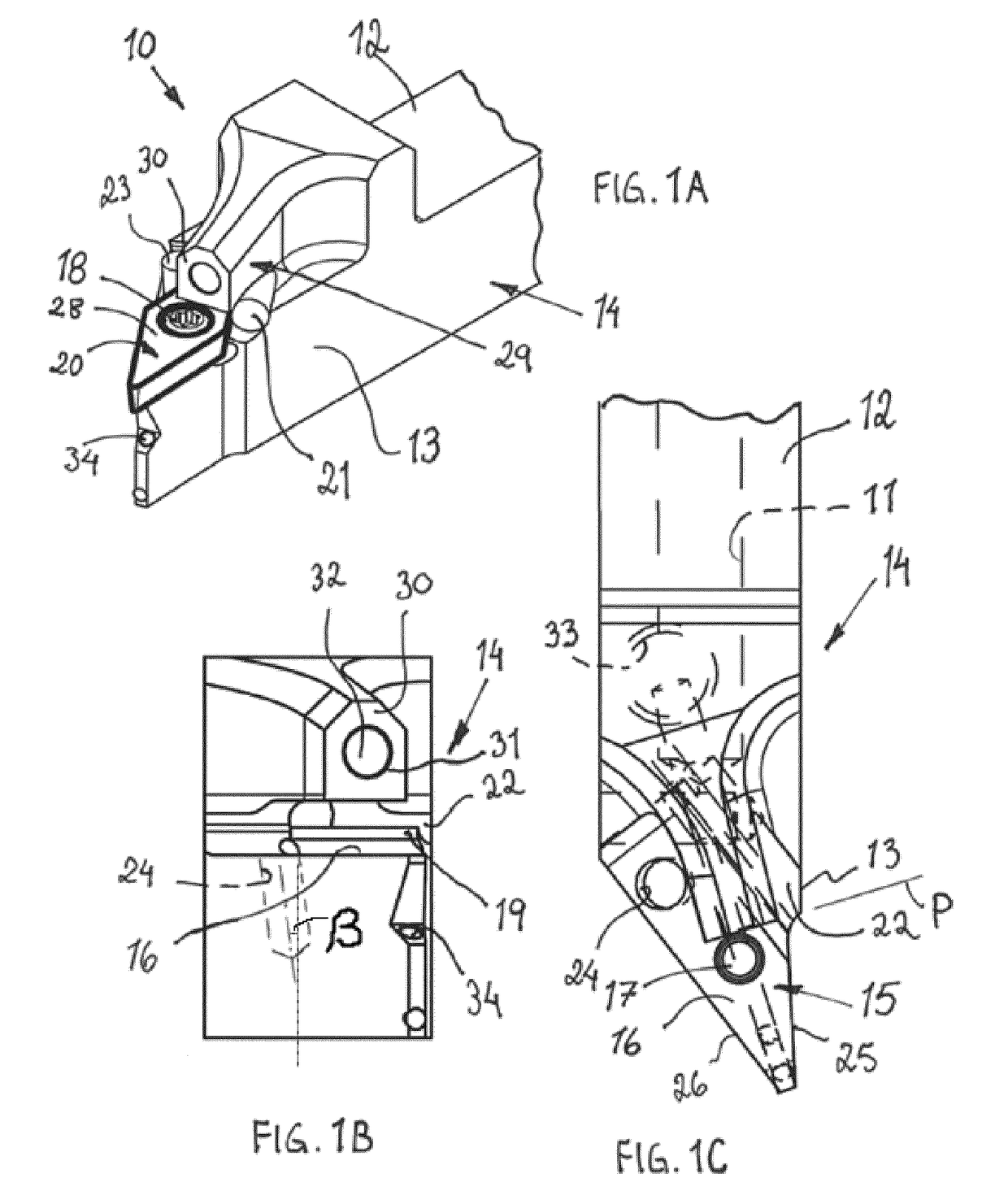
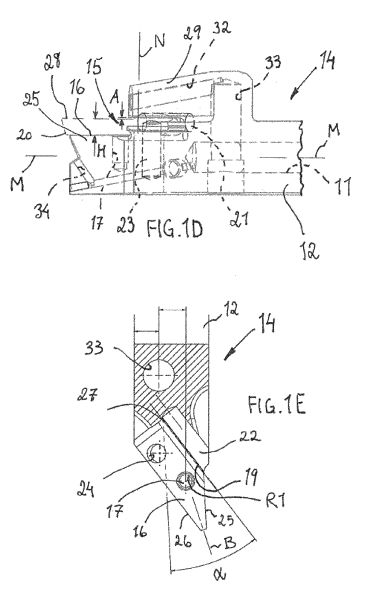
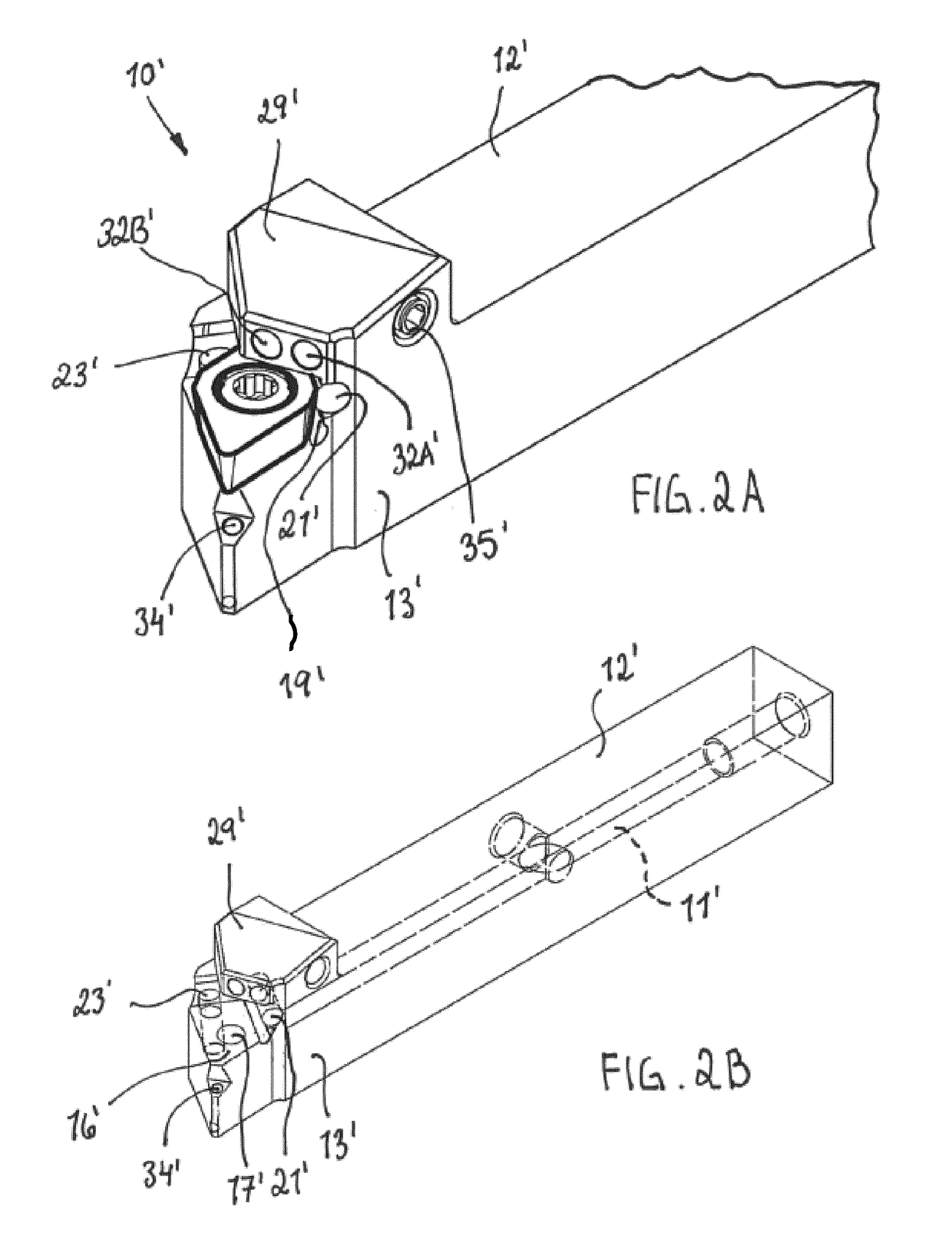
[0038]Reference is made to FIGS. 1A-1E showing a cutting tool 10 having a coolant conduit 11 in accordance with an aspect of the present invention. The shown cutting tool 10 may be a turning tool for external metal machining, preferably for use in a Swiss-type lathe. A Swiss-type lathe is a variety of turning machine that feeds the stock through a guide bushing. This means the turning tool can always cut the stock near the bushing, and therefore close to the point of support, no matter how long the workpiece. The machine feeds the work out of the spindle and past the tool as it moves. This makes the CNC Swiss-type particularly effective for long and slender turned parts. Typically, on the Swiss machine, the turning tool is stationary and the workpiece advances. Normally, a cutting tool for a Swiss-type lathe is relatively small, for example less than 20 cm from end to end and less than 3 cm in height.

[0039]A cutting insert 20 suitable for the cutting tool can be of a single-sided (p...


PUM


Abstract

A cutting tool includes a tool holder body having a shank portion and a head portion. The head portion has an insert seat, wherein a cutting insert is detachably mounted by means of a locking member. The seat includes at least one bottom surface on which the cutting insert rests. A coolant conveying member is integral with the tool holder body. A normal (N; N′) to the at least one bottom surface intersects the coolant conveying member, such that the coolant conveying member at least partially covers the cutting insert. The coolant conveying member is spaced from the locking member and the cutting insert when viewed in side view.

Description

FIELD OF THE INVENTION[0001]The present invention relates to a cutting tool for metal chip removing machining and, more particularly, to such cutting tools having coolant flow channels.BACKGROUND[0002]It is advantageous to deliver a coolant closely to a cutting area where interaction between a cutting edge and a workpiece takes place. By using a cutting tool having a coolant supply, a coolant can be directed to a cutting edge of the cutting insert for minimizing the heat accumulated due to the interaction of a cutting insert with the machined workpiece. Conventional techniques for providing lubrication and / or coolant to cutting edges of cutting inserts typically involve introducing the coolant via openings in a tool holder for the cutting insert, or via spray nozzles directed at the cutting edges such as in WO 2010 / 095124 A1, wherein a nozzle is shiftable relative to a member body, between a first, extended position and a second, retracted position. The coolant conveying member usua...

Claims


Application Information

Patent Timeline
Patent Type & Authority Applications(United States)
IPC IPC(8): B23B27/10B23B27/16
CPCB23B27/10B23B27/1662B23B2205/12
Inventor LARSSON, ANDREAS J.THELIN, JIMMYJONSSON, MATS
Owner SECO TOOLS AB
Learn More