Variable displacement swash plate type piston pump

Active Publication Date: 2019-01-31
TOYOTA IND CORP
View PDF0 Cites 1 Cited by
  • Summary
  • Abstract
  • Description
  • Claims
  • Application Information

AI Technical Summary

Benefits of technology

[0007]When the piston pump having the above-described configuration limits the inclination angle of the swash plate, the protrusion comes into contact with the stopper of the second housing member after being moved by receiving force from the control piston. Therefore, the vicinity of the stopper in the second housing member is a section on which stress tends to concentrate relatively easily. That is, unless sufficient sealing performance is ensured

Problems solved by technology

The opposite surface of the swash plate from the surface that contacts the control piston of the pro

Method used


Image

  • Variable displacement swash plate type piston pump
  • Variable displacement swash plate type piston pump
  • Variable displacement swash plate type piston pump

Examples


Example

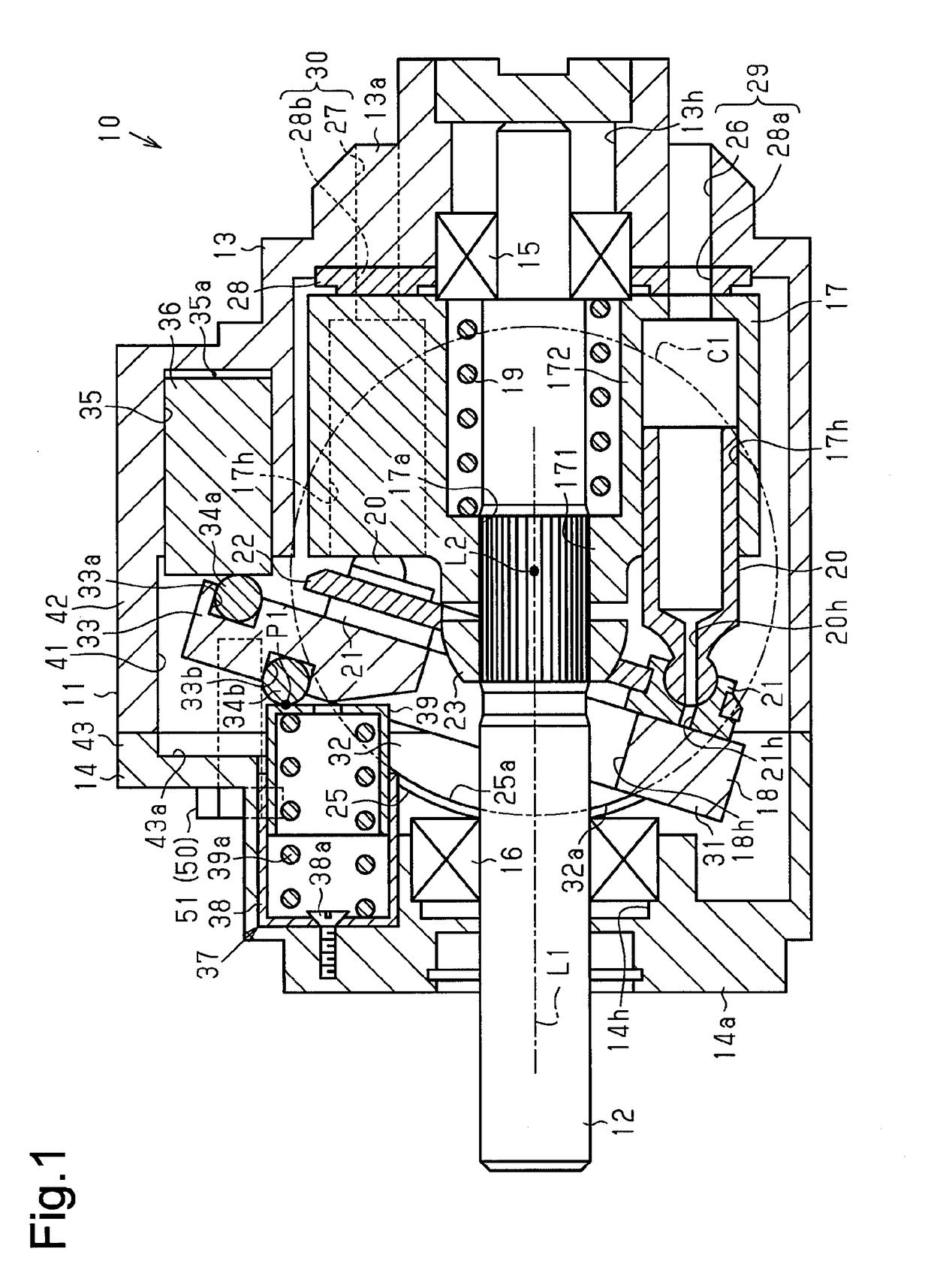
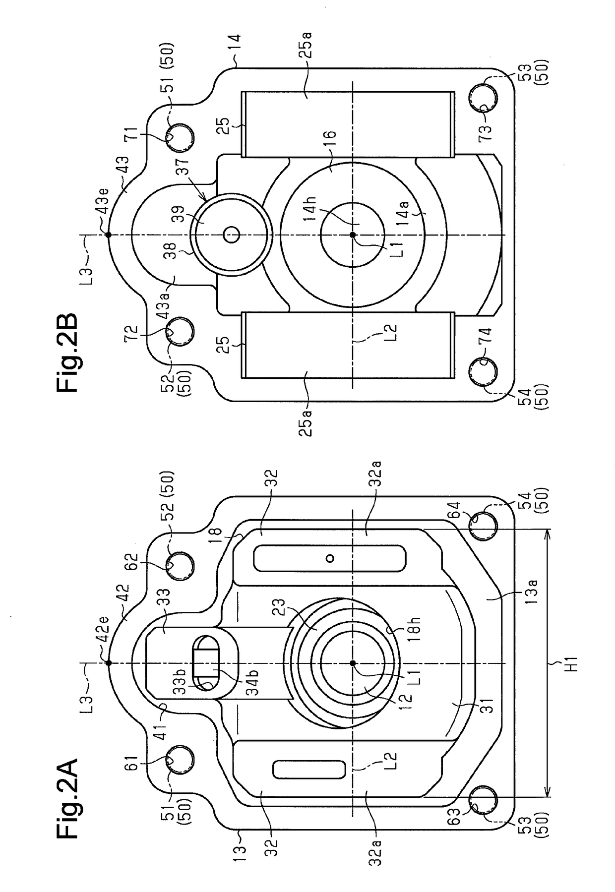
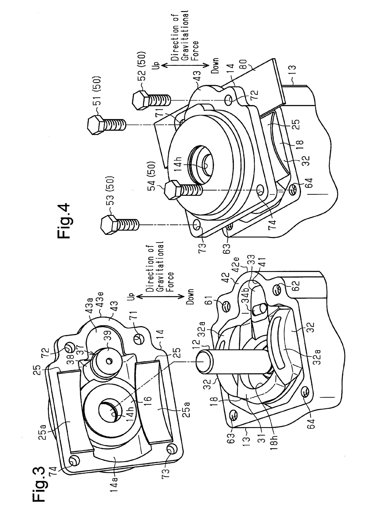
[0015]A variable displacement swash plate type piston pump according to one embodiment will now be described with reference to FIGS. 1 to 4. The piston pump of the present embodiment is used as a hydraulic pump mounted in an engine type forklift.

[0016]As shown in FIG. 1, a variable displacement swash plate type piston pump 10 includes a housing 11 and a rotary shaft 12. The rotary shaft 12 is rotationally supported by the housing 11 and has a rotational axis L1. The housing 11 has a first housing member 13 and a second housing member 14 both having a tubular shape with a bottom. The second housing member 14 is coupled to the open end of the first housing member 13. The first housing member 13 and the second housing member 14 are joined to each other with the open ends facing and contacting each other.

[0017]A bottom wall 13a of the first housing member 13 has an insertion hole 13h. A section of the rotary shaft 12 corresponding to the first housing member 13 is inserted into the inse...


PUM


Abstract

A variable displacement swash plate type piston pump includes first and second housing members fastened to each other by fastening members, a rotary shaft, a swash plate. A section of the inner circumferential surface of the first housing member has a recess. A bulging portion is arranged in a section of the outer circumferential wall of the first housing member. A section of the outer circumferential wall of the second housing member has a closing portion that closes the opening of the recess. The fastening members include first and second fastening members arranged at positions that are on the opposite sides of the recess, inside the width of the swash plate in a direction along the inclination axis of the swash plate, and closer to the rotary shaft than the distal ends of the bulging portion and the closing portion in the bulging direction.

Description

TECHNICAL FIELD[0001]The present invention relates to a variable displacement swash plate type piston pump.BACKGROUND ART[0002]Patent Document 1, for example, discloses a conventional variable displacement swash plate type piston pump. The piston pump is capable of changing displacement of hydraulic oil (hydraulic fluid). The piston pump is used as, for example, a hydraulic pump mounted in an engine type forklift. A rotary shaft is rotationally supported in the housing of the piston pump. A cylindrical cylinder block is arranged in the housing. The rotary shaft is inserted into the cylinder block. The cylinder block is configured to be rotational integrally with the rotary shaft and has cylinder bores around the rotary shaft. The cylinder bores each accommodates a piston. A shoe is arranged at the end of each piston. The shoes are held by a retainer plate.[0003]A swash plate is accommodated in the housing and has an angle of inclination (an inclination angle) changeable with respect...

Claims


Application Information

Patent Timeline
IPC IPC(8): F04B1/32F04B1/20F04B53/16
CPCF04B1/324F04B1/2078F04B53/16F04B1/2064
Inventor MATSUO, TSUTOMUYOKOMACHI, NAOYAUEDA, YUKIUNO, TAKASHI
Owner TOYOTA IND CORP
Why Eureka
Try Eureka