Apparatus and method for measuring cloud point pressure and density of supercritical CO2 microemulsion system

A technology of cloud point pressure and microemulsion, applied in the direction of measuring fluid pressure, measuring device, specific gravity measurement, etc., can solve the problems of many operation steps, high cost, time-consuming and laborious experiments, etc., achieve precise control of volume change and reduce manufacturing cost , the effect of simple structure

Inactive Publication Date: 2016-08-24
CHINA UNIV OF PETROLEUM (EAST CHINA)
View PDF2 Cites 4 Cited by
  • Summary
  • Abstract
  • Description
  • Claims
  • Application Information

AI Technical Summary

Problems solved by technology

[0005] Literature (Petrochemical Industry, 2013, 42, 303-307) has reported that the use of visible phase reactors for supercritical CO 2 The study of microemulsion phase behavior, this device is to change the volume of the visible kettle by manually rotating the piston, so as to obtain the cloud point pressure. This method has the following problems: First, use the manual rotating piston to conduct experiments. Once the pressure is greater than 10MPa , the rotation of the piston will be very difficult, and the experiment will be time-consuming and laborious; secondly, the structure of the equipment is complex, not only the manufacturing cost is high, but also there will be big problems in the guarantee of sealing; thirdly, in the judgment of the cloud point pressure, it is different from the current literature Like many reports, the method of visual inspection is used, the accuracy of the meas

Method used


Image

  • Apparatus and method for measuring cloud point pressure and density of supercritical CO2 microemulsion system
  • Apparatus and method for measuring cloud point pressure and density of supercritical CO2 microemulsion system
  • Apparatus and method for measuring cloud point pressure and density of supercritical CO2 microemulsion system

Examples


Embodiment 1

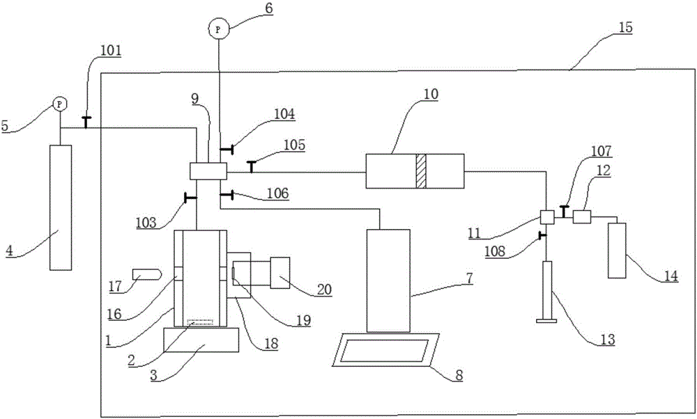
[0076] Control the temperature at 50°C, weigh 0.01g of surfactant sodium bis(2-ethylhexyl) succinate sulfonate (AOT), dissolve it in a mixed solvent composed of 1g of water and 10g of ethanol, and add it to a visual container , adjust the electromagnetic stirring speed to 100rad / min, and the CO in the gas storage tank 2 Into the visible container, until the pressure in the visible container is 19MPa, the added CO 2 mass, i.e. m 2 -m 3 The value is 85.0g, the volume of the visible container is increased through the intermediate container, and the curve of the system pressure and the resistance value of the photoresistor is recorded as figure 2 As shown, it can be concluded that the cloud point pressure of the system is 10.2MPa, restore the initial state of the visible container, increase the volume of the visible container through the intermediate container again until the pressure reaches 10.2MPa, and a total of 27.2mL of water is discharged from the intermediate container,...

Embodiment 2

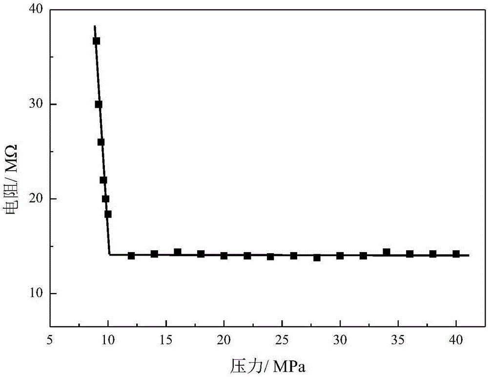
[0078] Control the temperature at 50°C, weigh 0.02g of surfactant sodium bis(2-ethylhexyl) succinate sulfonate (AOT), dissolve it in a mixed solvent composed of 1g of water and 10g of ethanol, and add it to a visual container In the process, the electromagnetic stirring speed is adjusted to 200rad / min, and the CO in the gas storage tank is 2 Into the visible container, until the pressure in the visible container is 19MPa, the added CO 2 mass, i.e. m 2 -m 3 The value is 86.2g, the volume of the visible container is increased through the intermediate container, and the curve of the system pressure and the resistance value of the photoresistor is recorded as image 3 As shown, it can be concluded that the cloud point pressure of the system is 13.6MPa, restore the initial state of the visible container, increase the volume of the visible container through the intermediate container again until the pressure reaches 13.6MPa, and a total of 9.0mL of water is discharged from the int...

Embodiment 3

[0080] Control the temperature at 60°C, weigh 0.03g of surfactant sodium bis(2-ethylhexyl)succinate sulfonate (AOT), dissolve it in a mixed solvent composed of 1g of water and 10g of ethanol, and add it to a visual container In the process, the electromagnetic stirring speed is adjusted to 500rad / min, and the CO in the gas storage tank is 2 Into the visible container, until the pressure in the visible container is 19MPa, the added CO 2 mass, i.e. m 2 -m 3The value is 85.2g, the volume of the visible container is increased through the intermediate container, and the curve of the system pressure and the resistance value of the photoresistor is recorded as Figure 4 As shown, it can be concluded that the cloud point pressure of the system is 16.0MPa, restore the initial state of the visible container, increase the volume of the visible container through the intermediate container again until the pressure reaches 16.0MPa, and a total of 0.72mL of water is discharged from the int...


PUM

PropertyMeasurementUnit
Volumeaaaaaaaaaa
Resistanceaaaaaaaaaa

Abstract

The invention discloses an apparatus and method for measuring the cloud point pressure and density of a supercritical CO2 microemulsion system. A magneton is arranged in a visual container, an electronic stirrer is arranged under the visual container, and the upper portion of the visual container is connected with a five-way valve. A quartz window is arranged on each of two parallel sides on the lower portion of the visual container, a light source is arranged on the outer side of one quartz window, and an opaque chamber is arranged on the outer side of the other quartz window. A photoresistor connected with a universal meter is arranged in the opaque chamber, and a CO2 gas cylinder is connected with the five-way valve. A second pressure transducer is connected to the five-way valve, one end of an intermediate container is connected to the five-way valve, and the other end of the intermediate container is connected with a three-way valve. A gas tank is connected with the five-way valve, one end of a high-pressure plunger pump is connected to the three-way valve, and the other end of the high-pressure plunger pump is connected with a water storage tank. A liquid volume metering device is connected with the three-way valve. The cloud point pressure of a supercritical CO2 microemulsion system and the density of the supercritical CO2 microemulsion system under the cloud point pressure can be obtained under same condition, the influence of minimal difference in parallel experiment processes can be minimized, and important basic data for designing construction scheme of an oil field can be provided.

Description

technical field [0001] The invention relates to the field of petroleum engineering and process technology, in particular to a method for measuring supercritical CO 2 Device and method for cloud point pressure and density of microemulsion system. Background technique [0002] Supercritical CO 2 Microemulsion systems have been widely used in the fields of extraction, organic synthesis, nanomaterial preparation and cleaning, and have shown excellent performance. In terms of tertiary oil recovery, CO 2 Oil displacement technology can effectively develop low permeability and heavy oil reservoirs. With the deepening of research, CO 2 There are more and more applications in oilfield exploitation, and field tests have been started in Jiangsu, Zhongyuan, Daqing and Shengli oilfields in China. In foreign countries, since the 1980s, CO 2 Oil displacement technology has been successfully applied in low-permeability reservoirs in the United States, the former Soviet Union, Canada a...

Claims


Application Information

Patent Timeline
IPC IPC(8): G01L11/00G01N27/04G01N9/04
CPCG01L11/00G01N9/04G01N27/041
Inventor 宫厚健朱腾董明哲李亚军徐龙张涛胡航张烈邢瑞宋晓丹
Owner CHINA UNIV OF PETROLEUM (EAST CHINA)
Why Eureka
Try Eureka