
System and method for using wearable technology in manufacturing and maintenance

a wearable technology and manufacturing and maintenance technology, applied in the field of wearable devices for manufacturing and maintenance, can solve the problems of inconvenient stopping work and climbing back to access documents, oversight or errors, and inability to automate assembly operations

Active Publication Date: 2019-01-31
GENERAL ELECTRIC CO
View PDF19 Cites 6 Cited by
  • Summary
  • Abstract
  • Description
  • Claims
  • Application Information

AI Technical Summary

Benefits of technology

The present invention relates to a system and method that uses a wearable device to provide instructions to a user and automatically document the completion of tasks based on signals from sensor-enabled tools. The system includes a tool with a sensor and a wearable device with a display and a computing device. The computing device provides visual instructions on the display of the wearable device and monitors the input from the sensor. The user wears the wearable device and performs the assembly operation on a component that forms a part of the machine. The computing device displays feedback to the user on the wearable device indicating the status of the assembly operation and stores a record of the status. The technical effect of this invention is to improve the efficiency and accuracy of assembly operations on machines that require precise tool usage and to provide a more convenient and efficient way of providing instructions to users performing assembly operations.

Problems solved by technology

These kinds of assembly operations are usually not automated and are typically performed by a technician or mechanic using hand tools.
One problem with this kind of documentation is that the digital or printed documents are not in the immediate vicinity of the person performing the work, where they can easily and quickly reference them.
Often the worker much climb a ladder or stand to perform the work, making it inconvenient to stop work and climb back to access the documents.
This reliance on the worker's memory can lead to oversight or errors when conducting the maintenance.
Another problem with conventional assembly procedures is that confirmation that all required operations (e.g. inserting parts, tightening fasteners, etc.) for a particular procedure have been completed is done manually.
This reliance on the worker's compliance with procedures can also lead to oversight or errors.
If the problem is discovered while the machine is in the possession of the manufacturer or maintainer, it can cause delays while troubleshooting and repair is performed.
If a problem is not discovered until it has left the manufacturer or maintainer, it can cause considerable problems, costs, and delays to both the customer and the manufacture or maintainer.

Method used


Image

  • System and method for using wearable technology in manufacturing and maintenance
  • System and method for using wearable technology in manufacturing and maintenance
  • System and method for using wearable technology in manufacturing and maintenance

Examples


Embodiment Construction

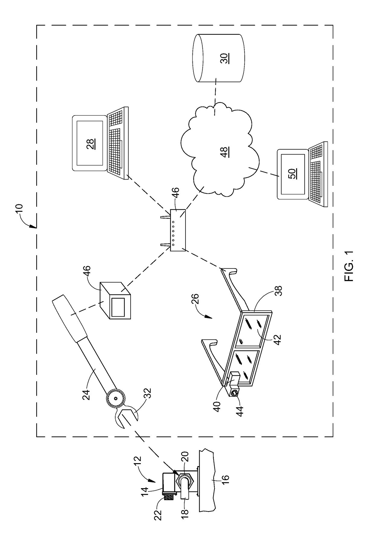
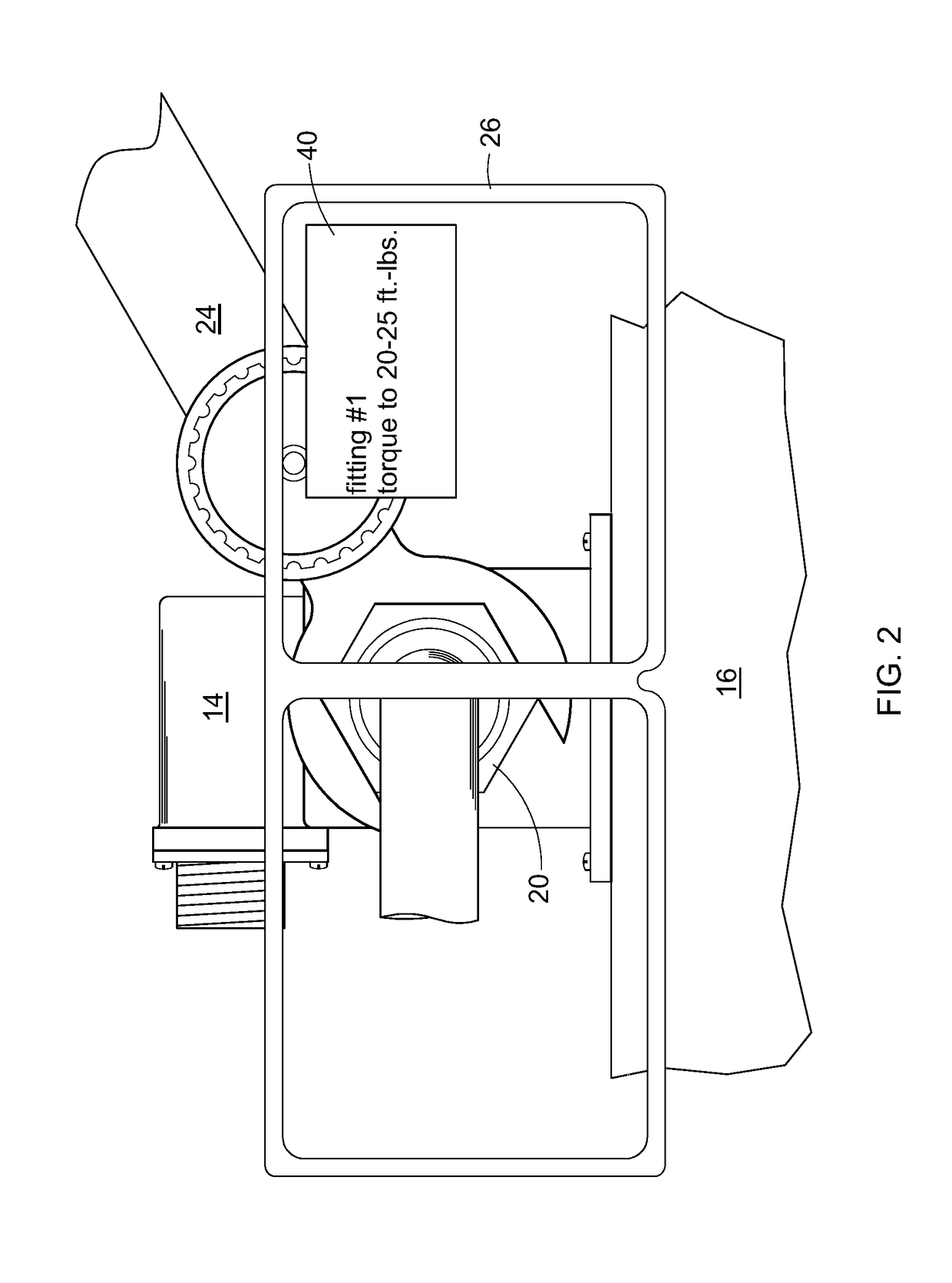
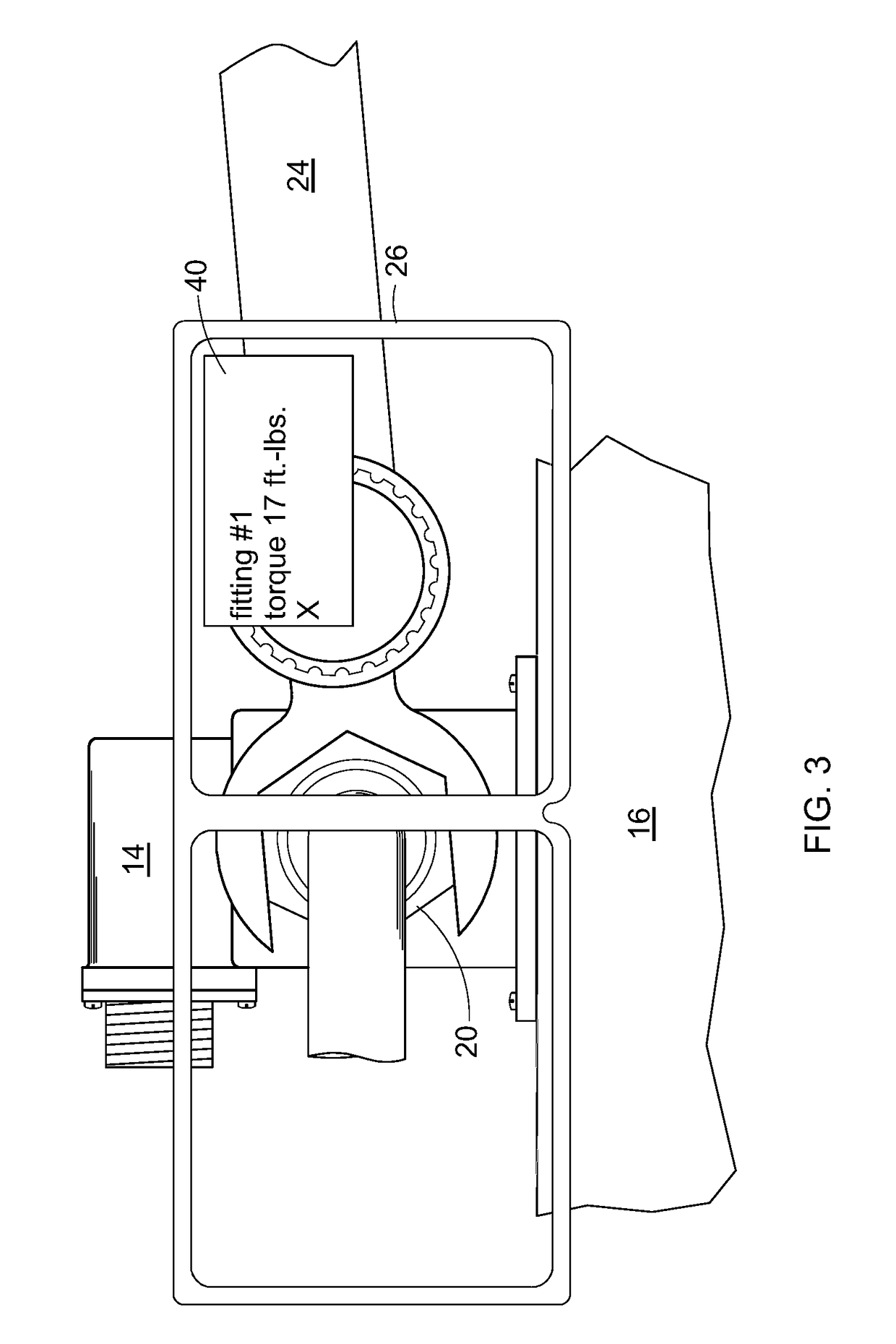
[0017]Referring to the drawings wherein identical reference numerals denote the same elements throughout the various views, FIG. 1 illustrates schematically a wearable-integrated assembly system 10 for manufacturing, maintenance, or repair of a machine 12. As used herein the term “machine” refers broadly to any assembly of two or more components into a larger unit which performs a defined function. The term “machine” may refer to a complete device or a subassembly which is incorporated into a larger device.

[0018]In the illustrated example, the machine 12 includes a fluid pressure sensor 14 mounted to a frame 16. A fluid conduit 18 is connected to the fluid pressure sensor using a conventional threaded fitting 20, e.g. an AN818 coupling nut, conventionally referred to as a “B-nut”. The fluid pressure sensor 14 further includes an electrical connector 22 for connection to a wiring harness (not shown). It will be understood that proper assembly of the machine 12 for a leak-free seal re...


PUM

PropertyMeasurementUnit
torqueaaaaaaaaaa
currentaaaaaaaaaa
areaaaaaaaaaaa

Abstract

An assembly system includes: a tool including a sensor; a wearable device including a display, and a computing device. The computing device is programmed to: a. provide visual instructions on the display of the device; b. monitor an input from the sensor; and c. in response to the input from the sensor: i. provide feedback to the user through the display, indicating a status of an operation of the tool; and ii. store a record of a status of an operation of the tool.

Description

BACKGROUND OF THE INVENTION[0001]This invention relates generally to manufacturing, assembly or disassembly, and maintenance, and more particularly to apparatus and methods for the use of wearable devices in manufacturing and maintenance.[0002]Manufacturing and maintenance processes for complex machines such as gas turbine engines often involves a series of assembly operations, which may involve putting two or more components together (literally “assembly”), as well as separating components (“disassembly”). For example, numerous components may be assembled to a machine using different types of fasteners and joints.[0003]These kinds of assembly operations are usually not automated and are typically performed by a technician or mechanic using hand tools.[0004]In the prior art, these kind of assembly processes typically rely on documentation such as assembly or maintenance manuals which are usually provided as printed copies or in static digital documents.[0005]One problem with this ki...

Claims


Application Information

Patent Timeline
Patent Type & Authority Applications(United States)
IPC IPC(8): G09B19/24G09B5/06G06F1/16G01L5/00G01L5/24
CPCG09B19/24G09B5/065G01L5/24G01L5/0042G06F1/163G06F3/011
Inventor ROBERTSON, TED LEWISILSE, ERIC ARTHURGEYMAN, MATTHEWBISCHOF, JOSEPH J.
Owner GENERAL ELECTRIC CO
Learn More