Active alignment correction for optical systems

Active Publication Date: 2019-01-31
QUALCOMM INC
View PDF7 Cites 0 Cited by
  • Summary
  • Abstract
  • Description
  • Claims
  • Application Information

AI Technical Summary

Benefits of technology

The patent describes a method and system for generating depth information based on captured image data and sensor data that can compensate for misalignment of optical devices. The method involves receiving the image data and sensor data, and generating a depth value that reflects the compensation for misalignment. The technical effect is the improved accuracy and reliability of depth information obtained from optical devices.

Problems solved by technology

The deflection can result in a misalignment of the first optical axis relative to the second optical axis.

Method used


Image

  • Active alignment correction for optical systems
  • Active alignment correction for optical systems
  • Active alignment correction for optical systems

Examples


Embodiment Construction

[0013]While the features, methods, devices, and systems described herein can be embodied in various forms, some exemplary and non-limiting embodiments are shown in the drawings, and are described below. Some of the components described in this disclosure are optional, and some implementations can include additional, different, or fewer components from those expressly described in this disclosure.

[0014]Relative terms such as “lower,”“upper,”“horizontal,”“vertical,”, “above,”“below,”“up,”“down,”“top” and “bottom” as well as derivative thereof (e.g., “horizontally,”“downwardly,”“upwardly,” etc.) refer to the orientation as then described or as shown in the drawing under discussion. Relative terms are provided for the reader's convenience. They do not limit the scope of the claims.

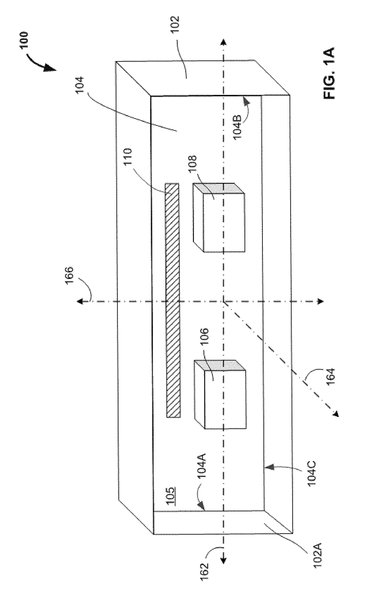
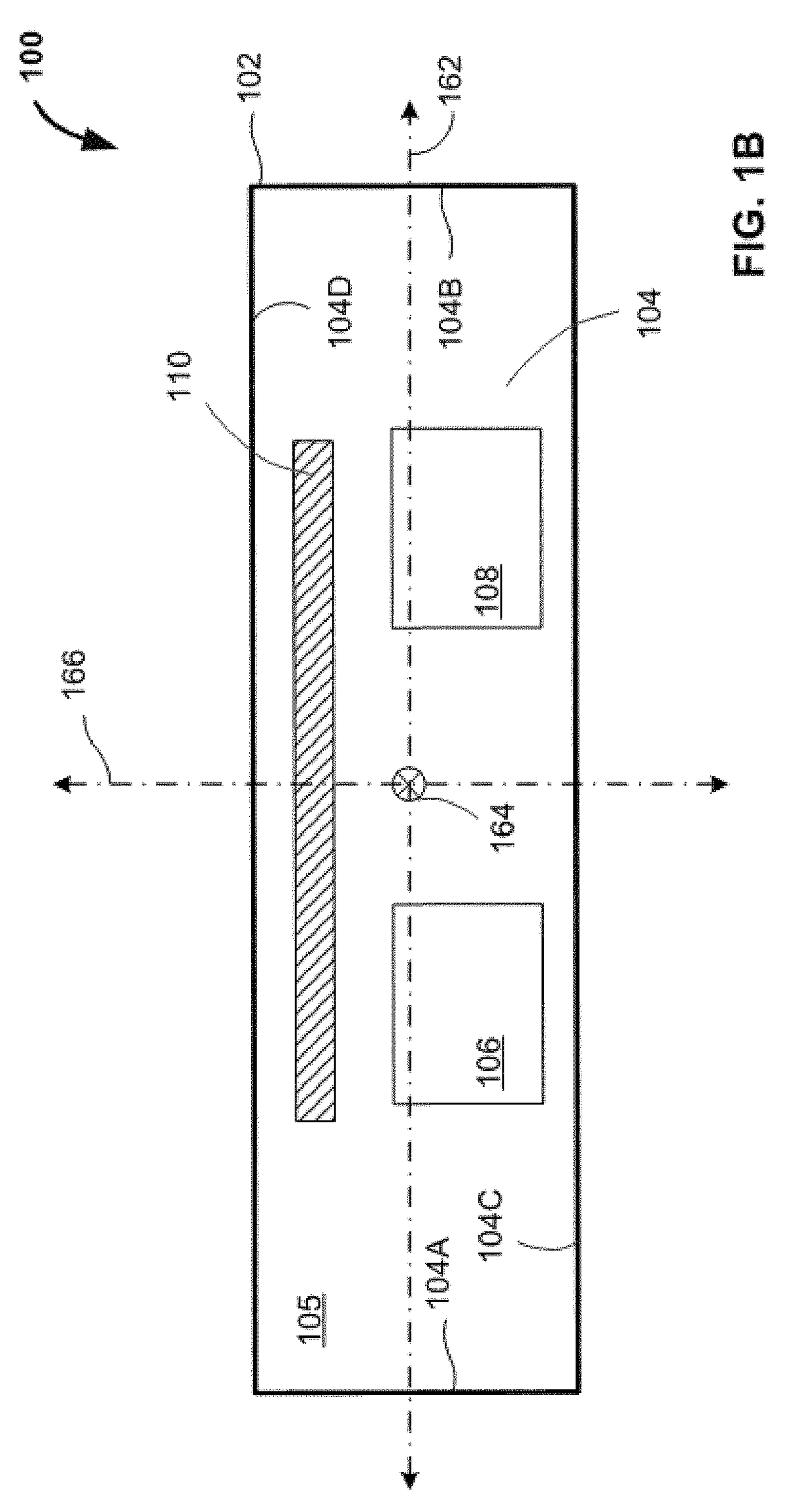
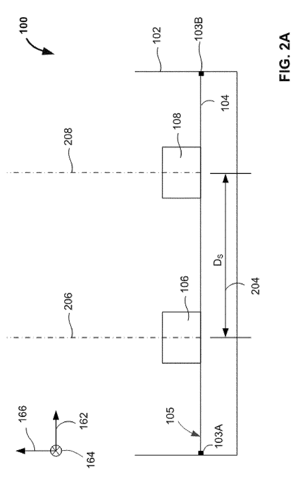
[0015]The inventors have determined that, for a device having two light sensing elements on a common substrate, any change in the positional relationship between the sensing elements can introduce errors into ...


PUM


Abstract

Methods, systems, and apparatuses are provided to compensate for a misalignment of optical devices within an imaging system. For example, the methods receive image data captured by a first optical device having a first optical axis and a second optical device having a second optical axis. The methods also receive sensor data indicative of a deflection of a substrate that supports the first and second optical devices. The deflection can result from a misalignment of the first optical axis relative to the second optical axis. The methods generate a depth value based on the captured image data and the sensor data. The depth value can reflect a compensation for the misalignment of the first optical axis relative to the second optical axis.

Description

BACKGROUNDField of the Disclosure[0001]This disclosure generally relates to optical systems and processes and more specifically relates to actively correcting misaligned components of an optical system.Description of Related Art[0002]Three-dimensional imaging and depth estimation technologies are of growing importance in many applications. To implement these three-dimensional imaging and depth estimation technologies, many optical systems incorporate multiple components that, when properly aligned and calibrated, capture image data characterizing a portion of an environment. To generate accurate depth values, the optical systems often maintain a specified positional relationship (e.g., a displacement, an orientation, etc.) between each of the components.SUMMARY[0003]Disclosed computer-implemented methods for generating at least one depth value can include receiving, by one or more processors, captured image data from a first optical device having a first optical axis or a second opt...

Claims


Application Information

Patent Timeline
IPC IPC(8): H04N13/00H04N5/225H04N5/232H04N13/02
CPCH04N5/2253H04N13/128H04N5/2252H04N5/23216G06T2200/04G06T2207/10024G06T2207/10028G06T2207/30252G06T7/521G06T5/80H04N23/51H04N23/54H04N23/62
Inventor NAING, HTETATANASSOV, KALIN MITKOVLINDNER, ALBRECHT JOHANNES
Owner QUALCOMM INC
Why Eureka
Try Eureka