Pressing-type screw

Active Publication Date: 2019-02-07
WU YI CHANG
View PDF13 Cites 0 Cited by
  • Summary
  • Abstract
  • Description
  • Claims
  • Application Information

AI Technical Summary

Benefits of technology

[0007]To solve the problem given above, an object of the present invention is to provide a pressing-type screw, such that by designing a structure of hollow space in the screw

Problems solved by technology

Nevertheless, in the use of the screw to perform an object-fixing work, a screwdriver is required

Method used


Image

  • Pressing-type screw
  • Pressing-type screw
  • Pressing-type screw

Examples


Embodiment Construction

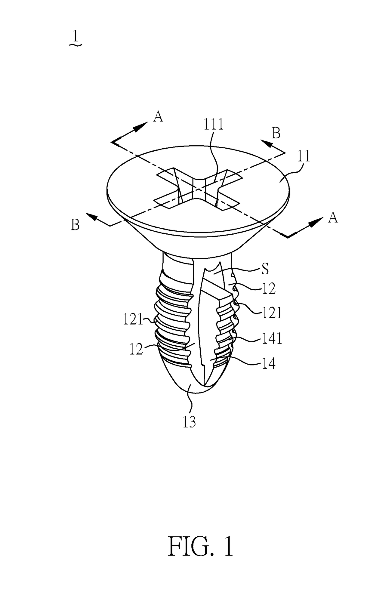
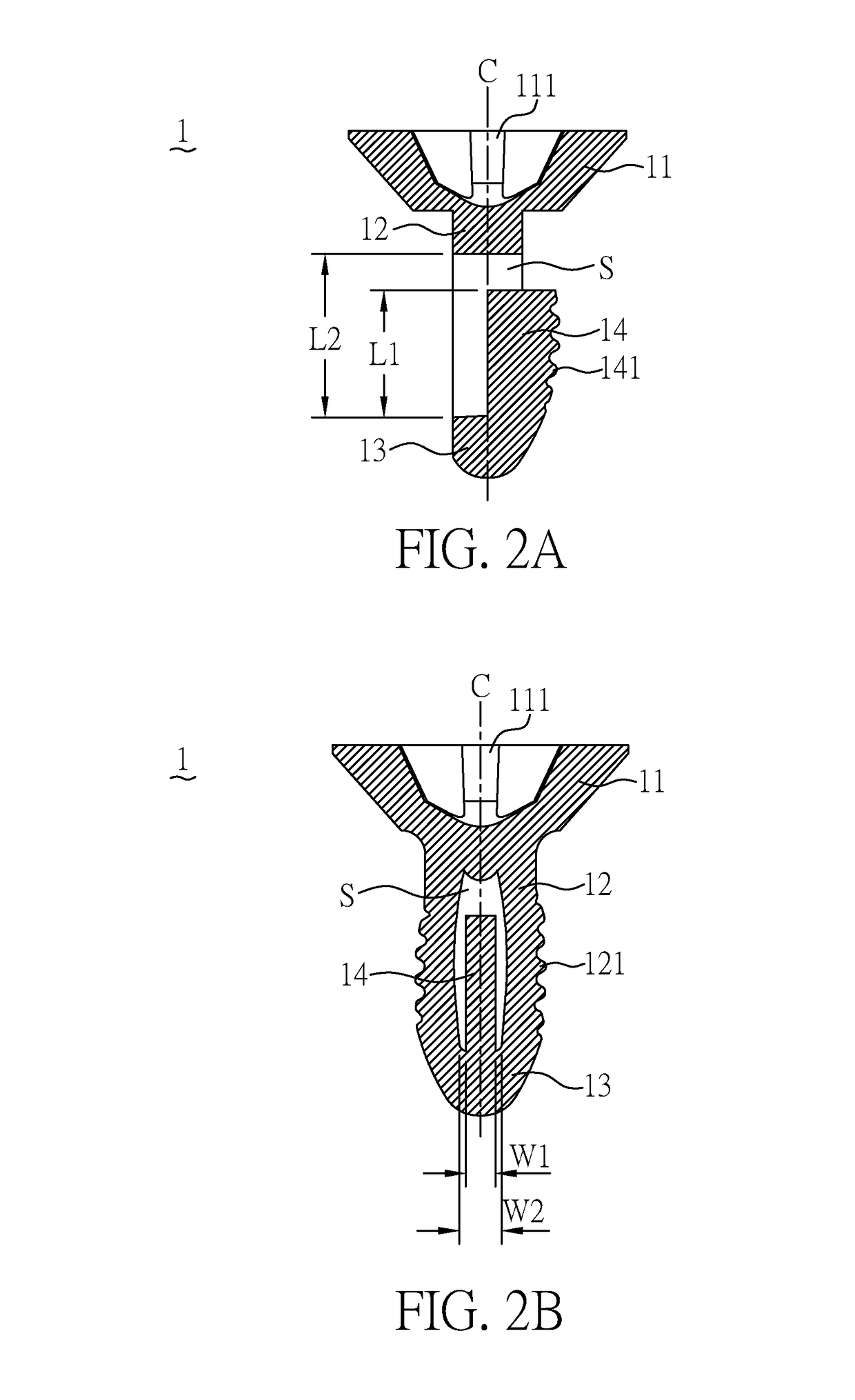
[0024]References are made to FIG. 1, a perspective view illustrating a pressing-type screw according to the present invention; FIG. 2A, a cross-sectional view taken along cutting line A-A of FIG. 1; and FIG. 2B, a cross-sectional view taken along cutting line B-B of FIG. 1. The pressing-type screw 1 comprises a screw-head component 11, two first drilling-fastening components 12, a drilling-head component 13, and a second drilling-fastening component 14.

[0025]According to the present invention, the screw-head component 11 is provided with a fastening slot 111. The two first drilling-fastening components 12 form an axis C passing through the center of the screw-head component 11. The two first drilling-fastening components 12 each has a top end in connection with the screw-head component 11, and each includes a first thread portion 121 formed on a surface of each of the two drilling-fastening components 12 and furthest away from the axis C. The drilling-head component 13 is in connect...


PUM


Abstract

A pressing-type screw includes a screw-head component, two first drilling-fastening components, and a drilling-head component. The screw-head component is provided with a fastening slot. The two first drilling-fastening components form an axis passing through the center of the screw-head component. The two first drilling-fastening components each has a top end in connection with the screw-head component, and each includes a first thread portion formed on a surface of each of the two first drilling-fastening components and furthest away from the axis. The drilling-head component is in connection with the bottom end of each of the two first drilling-fastening components. A hollow space is formed between the two first drilling-fastening components and the drilling-head component.

Description

CROSS REFERENCE TO RELATED APPLICATION[0001]This application claims the benefits of the Taiwan Patent Application Serial Number 106126307, filed on. Aug. 4, 2017, the subject matter of which is incorporated herein by reference.BACKGROUND OF THE INVENTION1. Field of the Invention[0002]The present invention relates to a pressing-type screw, and more particularly, to a pressing-type screw by designing a structure of hollow space in the screw so as to allow the screw to be pressed and fastened rapidly into an object.2. Description of Related Art[0003]Various fasteners are employed in the industrial design or interior design, as fixing components, for joining different objects. Namely, holes are drilled at two overlapped objects, and fasteners are used to fasten the same together. The fasteners may include rivets, nails, screws, and so forth, which fall within a mechanical fixing manner.[0004]It is noted that rivets relate to a destructive fixing measure, such that after the objects are ...

Claims


Application Information

Patent Timeline
IPC IPC(8): F16B35/04
CPCF16B35/041F16B33/006F16B19/004
Inventor WU, YI-CHANG
Owner WU YI CHANG
Why Eureka
Try Eureka