
Magnetic Screw and Plate Apparatus

a technology which is applied in the field of magnetic screw and plate apparatus, can solve the problems of pain and pressure on the spinal cord, many are insufficient to provide proper stability or otherwise aid in healing or treating the bones and connective tissues involved, and achieve the effect of preventing or reducing the deterioration of a non-fused intervertebral join

Active Publication Date: 2019-02-21
GOMBOC LLC
View PDF20 Cites 3 Cited by
  • Summary
  • Abstract
  • Description
  • Claims
  • Application Information

AI Technical Summary

Benefits of technology

The invention relates to a way to prevent or reduce damage to the spine where two non-fused vertebral joints meet. This is done by inserting bone screws into both vertebral bodies and aligning them in a way that creates a repulsive magnetic force between them. The technical effect of this method is to create a more stable and secure spine that reduces the risk of damage and pain caused by spinal degeneration.

Problems solved by technology

In vertebrates (including mammals such as humans), bones and connective tissues such as cartilage can break, fracture, or otherwise become damaged due to injury, age, heredity, or combinations thereof.
This is particularly true for cartilage and components of the intervertebral disc that can degenerate, resulting in pain and pressure on the spinal cord.
Prior apparatuses and methods for fixation or fusion of bones and joints to promote healing, relieve pain, and / or reduce future injury are generally known, but many are insufficient to provide proper stability or otherwise aid in healing or treating the bones and connective tissues involved.

Method used


Image

  • Magnetic Screw and Plate Apparatus
  • Magnetic Screw and Plate Apparatus
  • Magnetic Screw and Plate Apparatus

Examples


Embodiment Construction

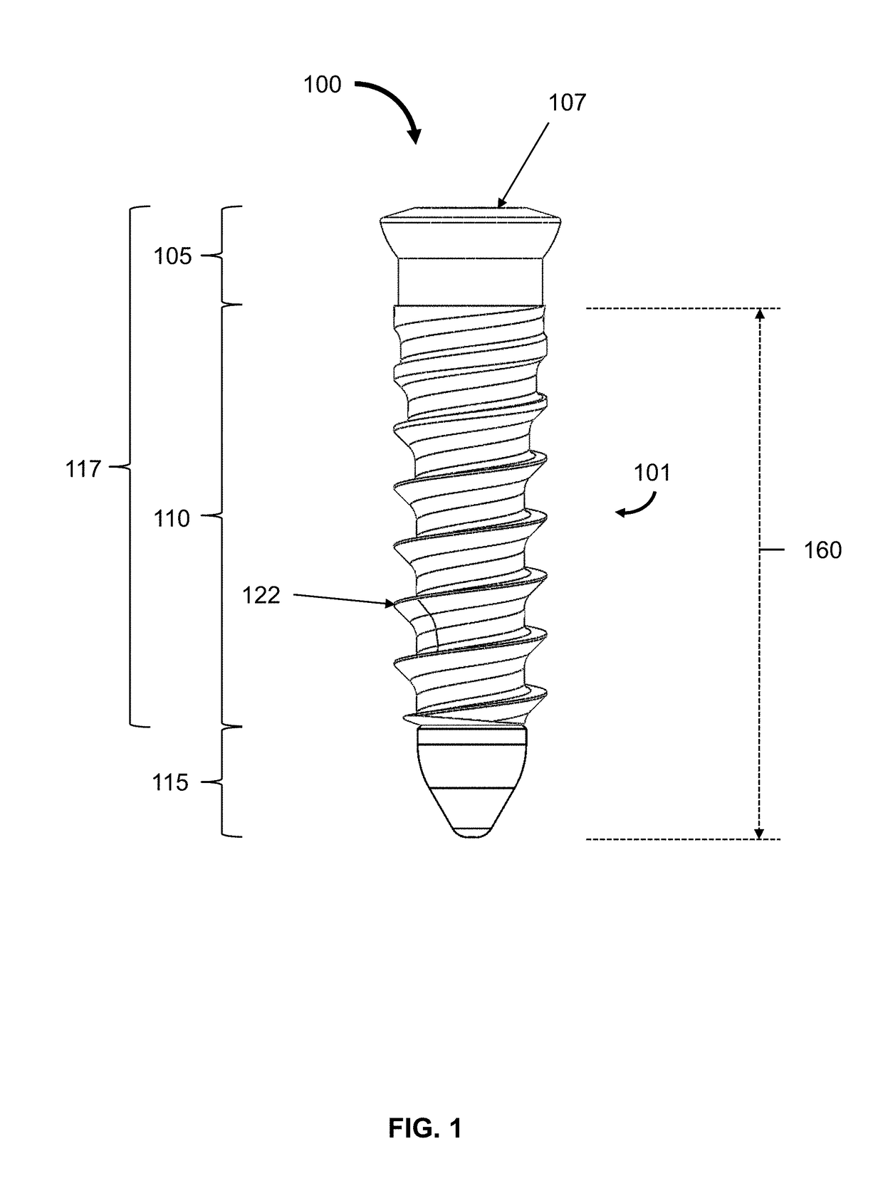
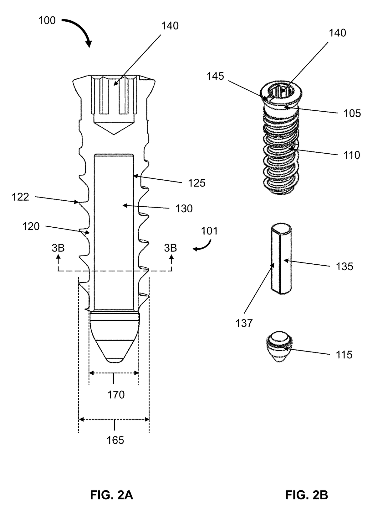
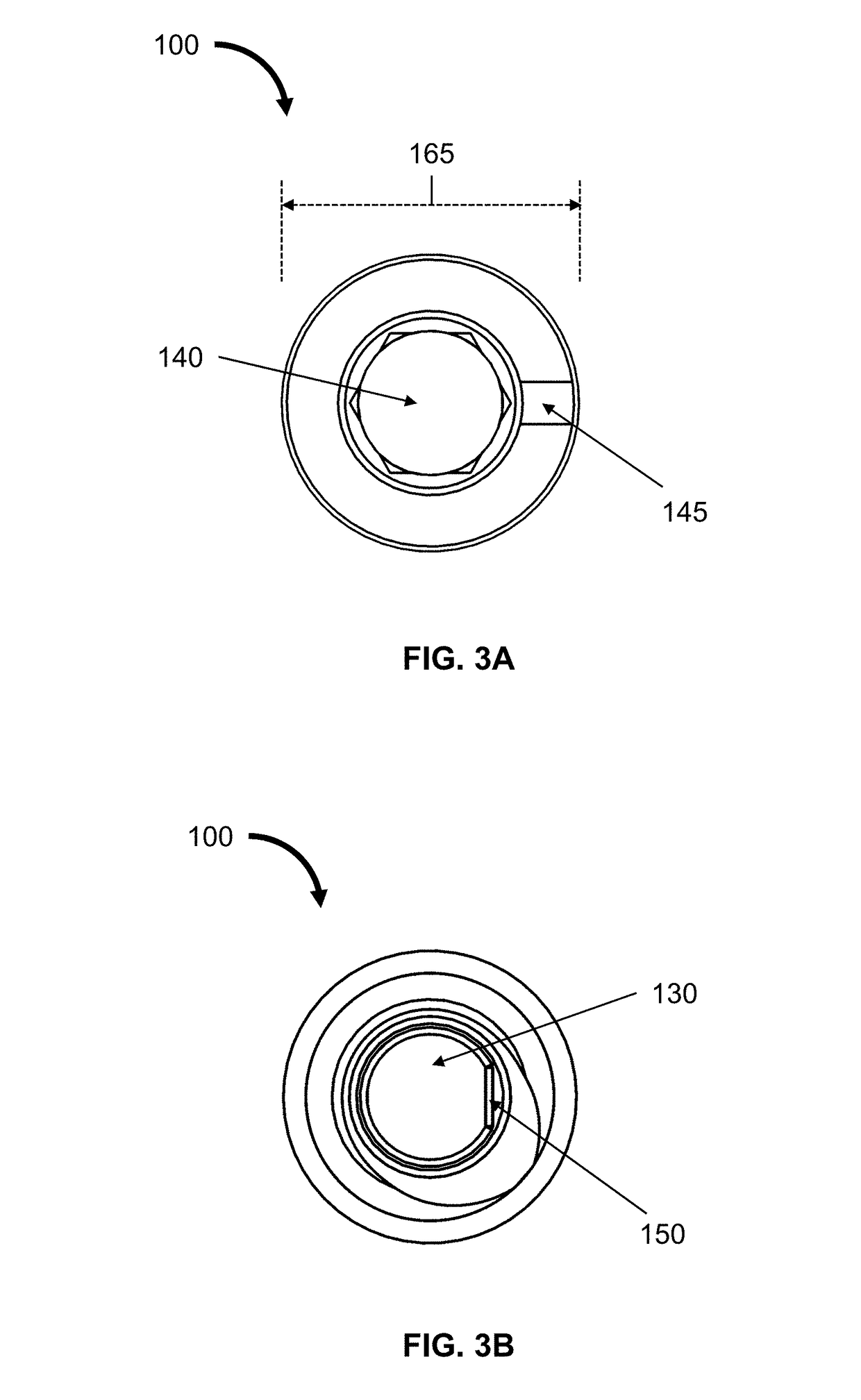
[0046]The present invention relates to a bone screw, plate, plate-and-screw apparatus, and methods thereof.

[0047]The bone screws of the present invention comprise a magnet, which generates a polarity. Upon insertion into bone, bone screws can be oriented such that their respective polarities create attractive or repulsive forces between the bone screws. Thus, if a bone screw is inserted into each of two adjacent bones, or into each of two different portions of the same bone, each bone screw can be oriented such that its polarity generates an attractive force between the bone screws that will pull the adjacent bones or the portions of the same bone towards each other; alternatively, each bone screw can be oriented such that its polarity generates a repulsive force between the bone screws that will push the adjacent bones or the portions of the same bone away from each other.

[0048]The bone screws of the invention can be used with a plate that can extend across adjacent bones or portio...


PUM


Abstract

A bone screw comprising a shaft, in which the shaft comprises a bore that is configured to fit a magnet. In addition, a bone plate comprising apertures that can fit the bone screw. The bone plate may be fastened to bone using the bone screws, and the bone screws may be oriented to generate attractive or repulsive forces.

Description

CROSS-REFERENCE TO RELATED APPLICATIONS[0001]This application claims the benefit of U.S. Provisional Application Ser. No. 62 / 545,572, filed on Aug. 15, 2017, which is hereby incorporated by reference in its entirety.BACKGROUND OF THE INVENTION[0002]In vertebrates (including mammals such as humans), bones and connective tissues such as cartilage can break, fracture, or otherwise become damaged due to injury, age, heredity, or combinations thereof. This is particularly true for cartilage and components of the intervertebral disc that can degenerate, resulting in pain and pressure on the spinal cord. Prior apparatuses and methods for fixation or fusion of bones and joints to promote healing, relieve pain, and / or reduce future injury are generally known, but many are insufficient to provide proper stability or otherwise aid in healing or treating the bones and connective tissues involved.SUMMARY OF INVENTION[0003]The present invention relates to devices and methods for use with bone and...

Claims


Application Information

Patent Timeline
Patent Type & Authority Applications(United States)
IPC IPC(8): A61B17/86A61B17/70
CPCA61B17/866A61B17/7059A61B17/8625A61B2017/00876A61B17/8023A61B17/8042A61B90/92A61B17/864A61B17/8014
Inventor COOK, STEPHEN D.HARRISON, MICHAEL C.NOLAN, LIAM P.
Owner GOMBOC LLC
Learn More