
Ink jet recording head and ink jet recording apparatus with nozzle member having an ink-repellent layer

a technology of ink-repellent layer and recording apparatus, which is applied in printing and other directions, can solve the problem that the ink that adheres to the discharge port face cannot be completely wiped off, and achieve the effect of preventing or reducing the deterioration of the ink-repellent layer and high array density

Active Publication Date: 2010-03-23
CANON KK
View PDF12 Cites 0 Cited by
  • Summary
  • Abstract
  • Description
  • Claims
  • Application Information

AI Technical Summary

Benefits of technology

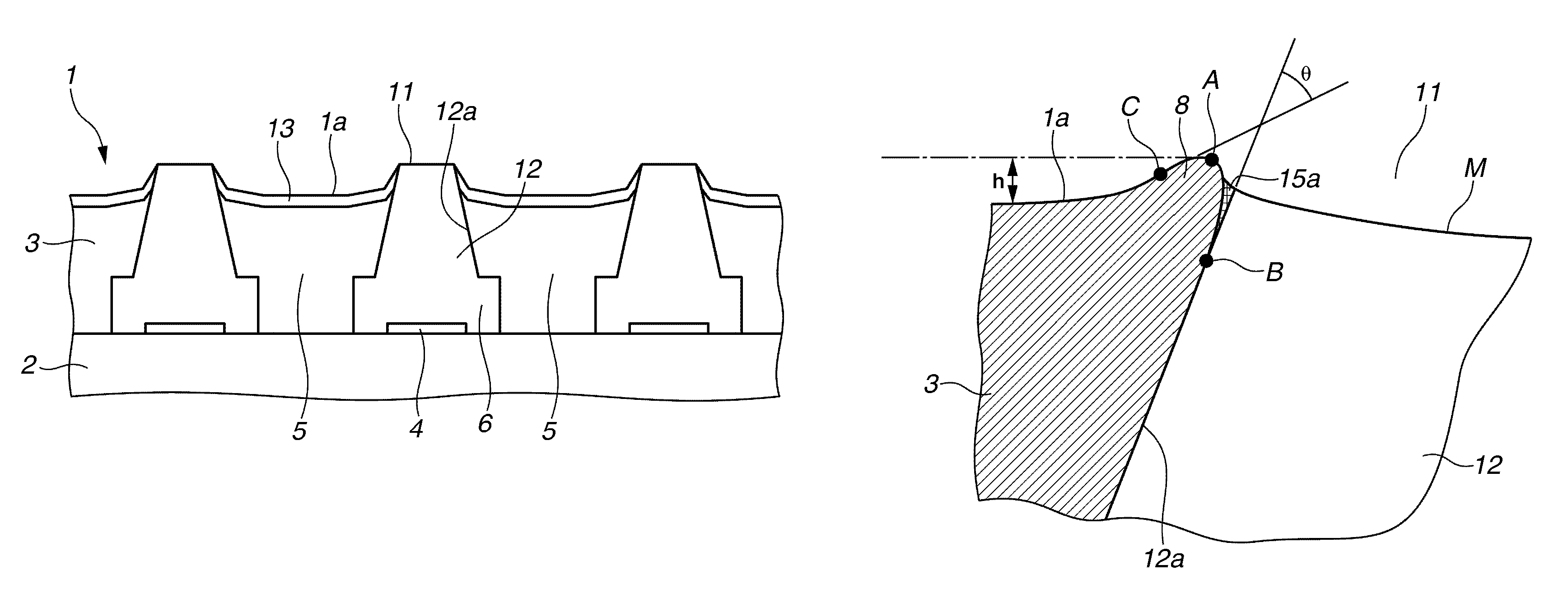
[0012]The present invention is directed to an ink jet recording head and an ink jet recording apparatus in which an ink discharge direction can be made stable by preventing or reducing the deterioration of an ink-repellent layer even in a case where pigment ink is discharged from a recording head having a high array density for discharging minute ink droplets.
[0015]According to an aspect of the present invention, since the projection portion is provided around the discharge port as described above, ink coagulation can hardly be generated in the nozzle even if pigment ink is used. Thus, the ink-repellent layer on the discharge port face is excellently maintained even if the wiping processing on the discharge port face is repeated. As a result, the displacement of a ink discharge direction caused by ink adhering to the discharge port face can effectively be prevented or reduced to facilitate stably discharging ink.

Problems solved by technology

However, the ink that adheres to the discharge port face cannot be completely wiped off even after the wiping process, so that the some ink still remains on the discharge port face in some cases.
The problem has recently been detected in a recording head having a high density array for discharging minute droplets using pigment ink to record a high-resolution image as described above.

Method used


Image

  • Ink jet recording head and ink jet recording apparatus with nozzle member having an ink-repellent layer
  • Ink jet recording head and ink jet recording apparatus with nozzle member having an ink-repellent layer
  • Ink jet recording head and ink jet recording apparatus with nozzle member having an ink-repellent layer

Examples


Embodiment Construction

[0027]Exemplary embodiments of the invention will be described in detail below with reference to the drawings.

[0028]First of all, a mechanism of deterioration of an ink-repellent property is described below in a case where an ink-repellent layer is formed on a discharge port face of an ink jet recording head using pigment ink as discharged ink.

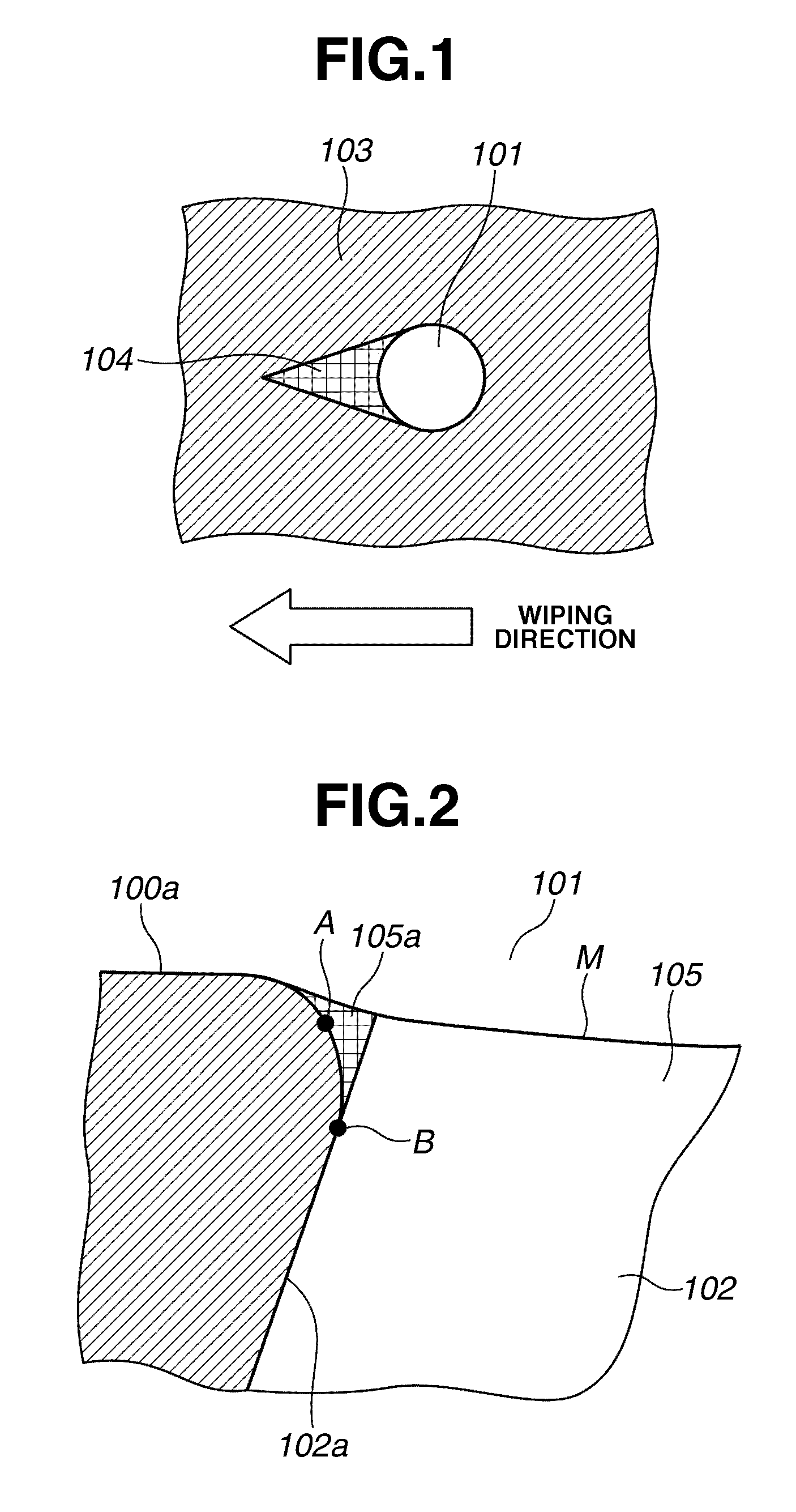
[0029]In order to analyze a mechanism of deterioration of an ink-repellent property, the inventor of the present invention observed a discharge port face of a conventional ink jet recording head, which does not have a projection portion around a discharge port, where a displacement of an ink discharge direction occurred. As a result of observation, an area 104 susceptible to wetting with ink was found to exist on a discharge port face, as illustrated in FIG. 1. In the area 104 susceptible to wetting, an ink-repellent layer 103 had been removed from the discharge port face. The area 104 susceptible to wetting is adjacent to a discharge port 101...


PUM


Abstract

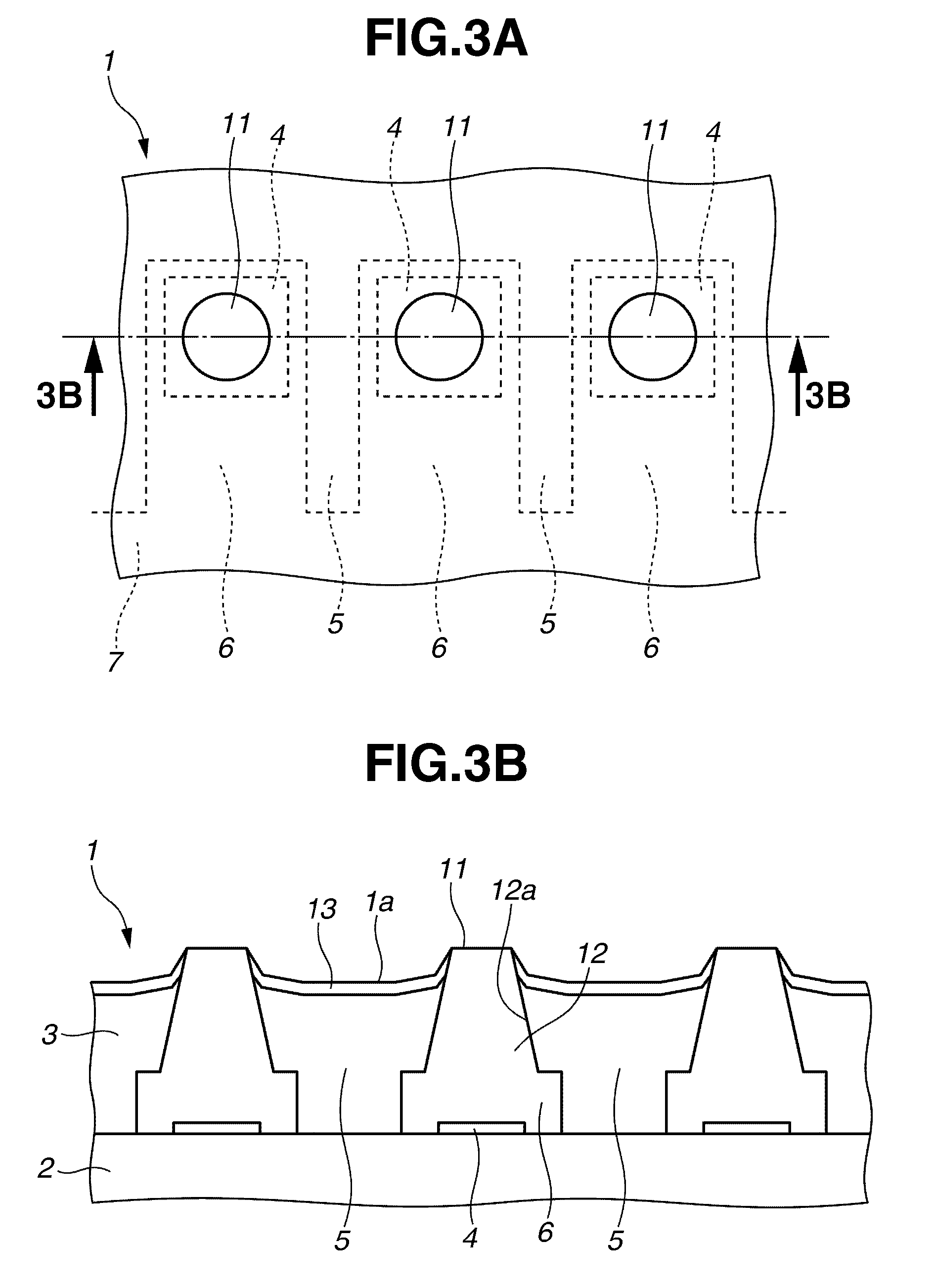
An inkjet recording head using pigment ink as discharged ink includes a nozzle member having a nozzle for discharging ink. The nozzle member has an ink-repellent layer forming a discharge port face having a discharge port that is an open end of the nozzle. The ink jet recording head further includes a projection portion positioned around the discharge port and protruding along a central axis of the nozzle with respect to the discharge port face. The nozzle, in a cross section passing through the central axis of the nozzle, has an outline shape provided with a curved line having a changing curvature radius. A point at which the curvature radius of the curved line is minimum is included in the projection portion and has a maximum height from the discharge port face in the cross section.

Description

BACKGROUND OF THE INVENTION[0001]1. Field of the Invention[0002]The present invention relates to an ink jet recording head adapted to perform recording on a recording medium by discharging ink from a discharge port, and to an ink jet recording apparatus including the ink jet recording head.[0003]2. Description of the Related Art[0004]An ink jet recording apparatus performs recording by discharging ink droplets from a discharge port provided in an ink jet recording head, and applying the ink droplets to a recording medium such as paper or resin sheet. A conventional ink jet recording head includes a substrate bearing an energy generating element, a flow path member bonded to the substrate for forming ink flow paths, and an orifice plate bonded to the flow path member and having an ink discharge port. The energy generating element is provided in a position corresponding to the ink flow path, which is used to generate energy to discharge ink. Examples of the energy generating element i...

Claims


Application Information

Patent Timeline
Patent Type & Authority Patents(United States)
IPC IPC(8): B41J2/14B41J2/135
CPCB41J2/1433B41J2/1606B41J2002/14475B41J2/135B41J2/16
Inventor MIZUTANI, MICHINARI
Owner CANON KK
Learn More