
Fuel cell stack

Inactive Publication Date: 2011-12-15
SAMSUNG SDI CO LTD
View PDF1 Cites 1 Cited by
  • Summary
  • Abstract
  • Description
  • Claims
  • Application Information

AI Technical Summary

Benefits of technology

[0011]The present invention provides a fuel cell stack for preventing or reducing deterioration of the membrane-electrode assembly by increasing a moisture content of an oxidizing agent provided to the fuel cell stack, without substantially increasing a volume of the fuel battery system or manufacturing costs.
[0021]The fuel cell stack according to exemplary embodiments of the present invention recycles moisture of the discharged oxidizing agent by using a moisture supplying flow path, such that a humidity of the supplying oxidizing agent may be increased. As a result, the whole membrane-electrode assembly may be maintained with appropriate humidity, such that deterioration of the membrane-electrode assembly may be suppressed or reduced, and the generating efficiency and life-span of the fuel cell stack may be improved. Also, the fuel cell stack does not include an additional humidifying device, such that a volume of the fuel battery system is small, manufacturing costs may be decreased, and an increase in a number of components may be minimized.

Problems solved by technology

However, when using the humidifying device, the volume of the fuel battery system is increased, manufacturing costs are increased, and a water supply source and a pump for supplying the water to the humidifying device are required.
Meanwhile, when air that is not humidified is introduced as is, the region that is initially supplied with the oxidizing agent becomes very dry with respect to the cathodes of the membrane-electrode assemblies, such that the membrane-electrode assemblies may be deteriorated.
The dry state can cause radicals generated during the operation of the membrane-electrode assembly to be sustained in the membrane-electrode assembly for a long time, such that deterioration of the membrane-electrode assembly may be accelerated.

Method used


Image

  • Fuel cell stack
  • Fuel cell stack
  • Fuel cell stack

Examples


Embodiment Construction

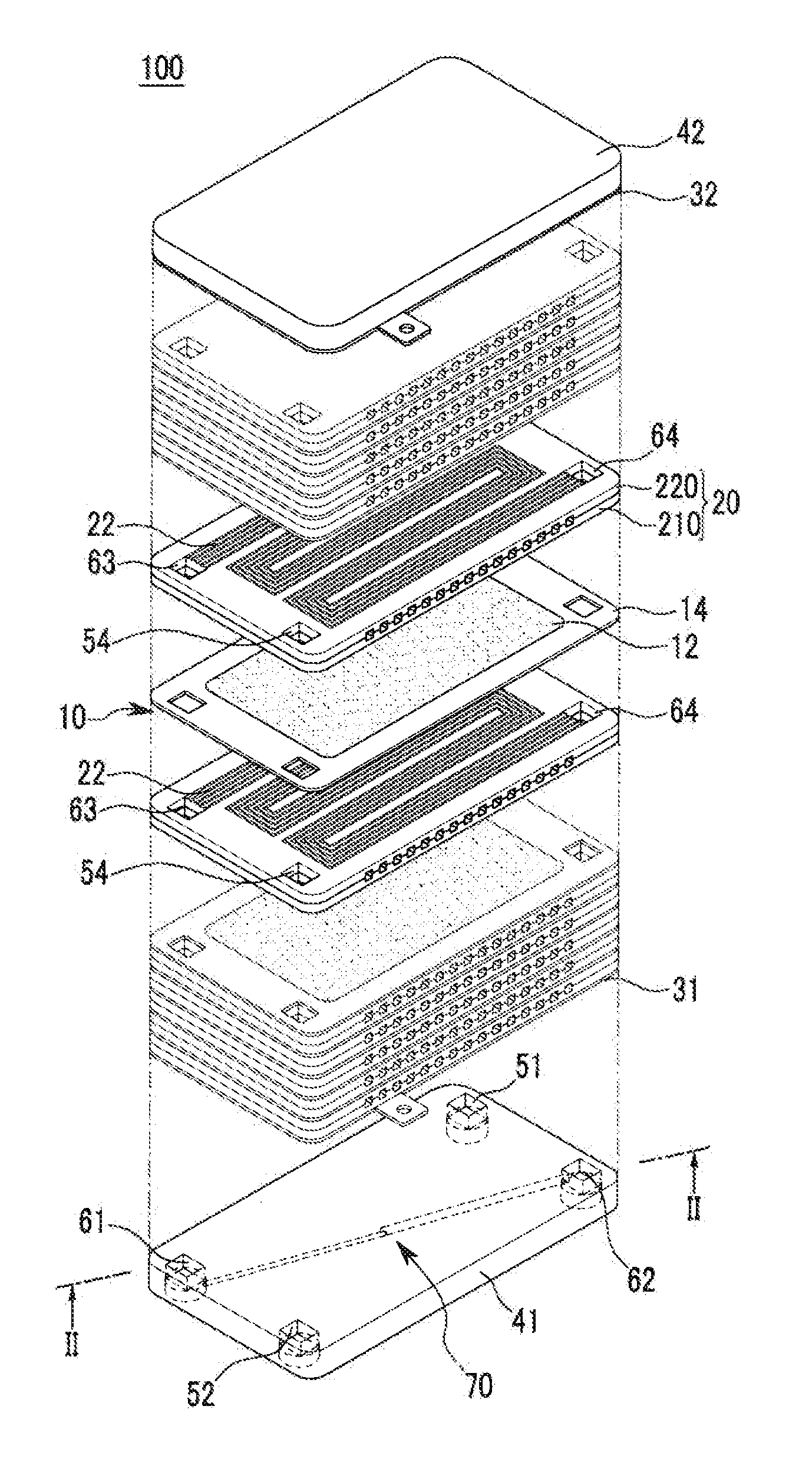
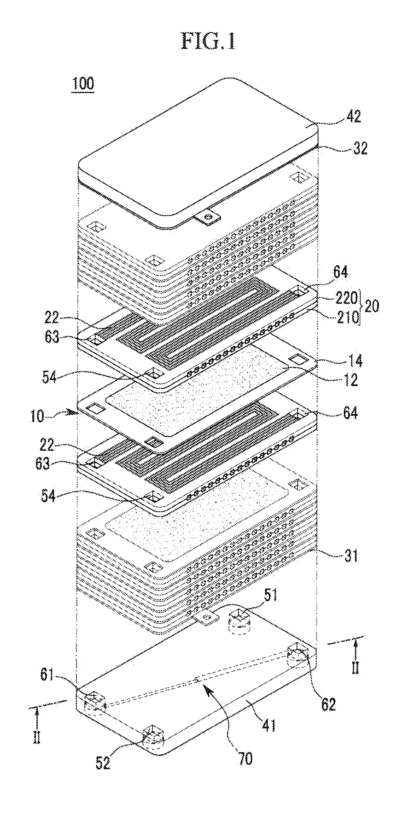
[0031]The present invention will be described more fully hereinafter with reference to the accompanying drawings, in which exemplary embodiments of the invention are shown. As those skilled in the art will recognize, the described embodiments may be modified in various different ways without departing from the spirit or scope of the present invention.

[0032]FIG. 1 is an exploded perspective view of a fuel cell stack according to a first exemplary embodiment of the present invention.

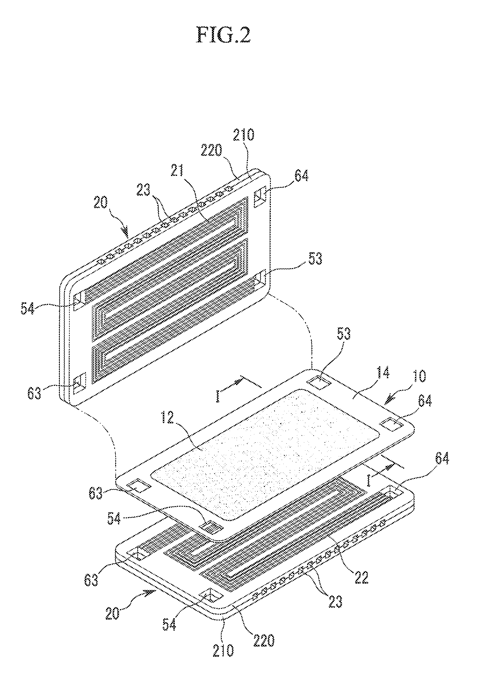
[0033]Referring to FIG. 1, a fuel cell stack 100 according to the first exemplary embodiment includes a plurality of membrane-electrode assemblies 10, a plurality of separators 20 positioned between the membrane-electrode assemblies 10, first and second current collecting plates 31 and 32 respectively positioned outside the outermost separators, and first and second end plates 41 and 42 respectively positioned outside the first and second current collecting plates 31 and 32.

[0034]The fuel cell stack 100 is...


PUM


Abstract

A fuel cell stack includes: a plurality of membrane-electrode assemblies; first and second end plates respectively positioned outside outermost ones of the membrane-electrode assemblies; and a plurality of separators respectively positioned between the membrane-electrode assemblies and between the outermost ones of the membrane-electrode assemblies and the first and second end plates. The first end plate includes an oxidizing agent inlet, an oxidizing agent outlet, and a moisture supplying flow path connecting the oxidizing agent inlet and the oxidizing agent outlet. The moisture supplying flow path includes a first end portion adjacent to the oxidizing agent outlet and a second end portion adjacent to the oxidizing agent inlet, the first end portion being larger than the second end portion and being a different distance away from a surface of the first end plate facing away from the second end plate than the second end portion.

Description

CROSS-REFERENCE TO RELATED APPLICATION[0001]This application claims priority to and the benefit of Korean Patent Application No. 10-2010-0055628 filed in the Korean Intellectual Property Office on Jun. 11, 2010, the entire contents of which are incorporated herein by reference.BACKGROUND[0002](a) Field[0003]The present invention relates to a fuel cell stack. More particularly, the present invention relates to an end plate for a fuel cell stack.[0004](b) Description of Related Art[0005]A fuel cell system includes a fuel cell stack that generates electrical energy using the electrochemical reaction between a fuel (hydrocarbon-based fuel, pure hydrogen, or reformed gas rich in hydrogen) and an oxidizing agent (air or pure oxygen). A direct oxidation type fuel cell uses a liquid or gas hydrocarbon-based fuel, and a polymer electrolyte type fuel cell uses pure hydrogen or a reformed gas rich in hydrogen.[0006]The fuel cell stack includes membrane-electrode assemblies (MEAs), separators p...

Claims


Application Information

Patent Timeline
IPC IPC(8): H01M8/24
CPCH01M8/0204Y02E60/50H01M2008/1095H01M8/04141Y02P70/50
Inventor LEE, JIN-HWALEE, CHI-SEUNGAN, SEONG-JINHAN, SANG-IISONG, KAH-YOUNG
Owner SAMSUNG SDI CO LTD
Learn More