
Internal magnetic traction device for the cervical seine

a magnetic traction and cervical spine technology, applied in the field of internal magnetic traction devices for the cervical spine, can solve the problems of pain and pressure on the spinal cord, many are insufficient to provide proper stability or otherwise aid in healing or treating the bones and connective tissues involved, and achieve the effect of preventing or reducing the deterioration of a non-fused intervertebral join

Active Publication Date: 2020-02-11
GOMBOC LLC
View PDF9 Cites 2 Cited by
  • Summary
  • Abstract
  • Description
  • Claims
  • Application Information

AI Technical Summary

Benefits of technology

The invention is a method to prevent deterioration of nonfused intervertebral joints that are above or below fused joints. The method involves inserting bone screws into the first and second vertebras, where the first vertebra may also have a fused joint with an adjacent vertebra. The bone screws are positioned in a way that creates a repulsive magnetic force between them, which helps to reduce degeneration of the nonfused joint.

Problems solved by technology

In vertebrates (including mammals such as humans), bones and connective tissues such as cartilage can break, fracture, or otherwise become damaged due to injury, age, heredity, or combinations thereof.
This is particularly true for cartilage and components of the intervertebral disc that can degenerate, resulting in pain and pressure on the spinal cord.
Prior apparatuses and methods for fixation or fusion of bones and joints to promote healing, relieve pain, and / or reduce future injury are generally known, but many are insufficient to provide proper stability or otherwise aid in healing or treating the bones and connective tissues involved.
Additionally, methods and devices for supplying traction forces are generally known, but do not provide consistent, continuous low magnitude traction forces in order to maintain disc height and health and to relieve acute and chronic cervical neck pain.

Method used


Image

  • Internal magnetic traction device for the cervical seine
  • Internal magnetic traction device for the cervical seine
  • Internal magnetic traction device for the cervical seine

Examples


examples

[0120]A series of finite element analyses were conducted using JMAG to study the magnetic forces that are generated when magnets are used in a cervical traction application. In these studies, four magnets are placed in a configuration depicted in FIGS. 24A and 24B. These magnets are 5 mm in diameter and 20 mm in length. The lower two magnets are 10 mm apart and the upper two magnets are 8 mm apart. The height difference between the upper and lower magnets is varied at 8, 10, and 12 mm.

[0121]The analyses determined the repulsion force that was created by the magnets in this configuration. The axial loads generated when the height difference between the upper and lower magnets is 8 mm, 10 mm, and 12 mm are provided in Tables 1, 2, and 3, respectively. These distances are the minimum axial distances for the example given; therefore, the axial loads that are generated represent the maximum axial forces. Values could be changed depending on the patient, for example, the anatomical dimens...


PUM

PropertyMeasurementUnit
outer diameteraaaaaaaaaa
heightaaaaaaaaaa
lengthaaaaaaaaaa

Abstract

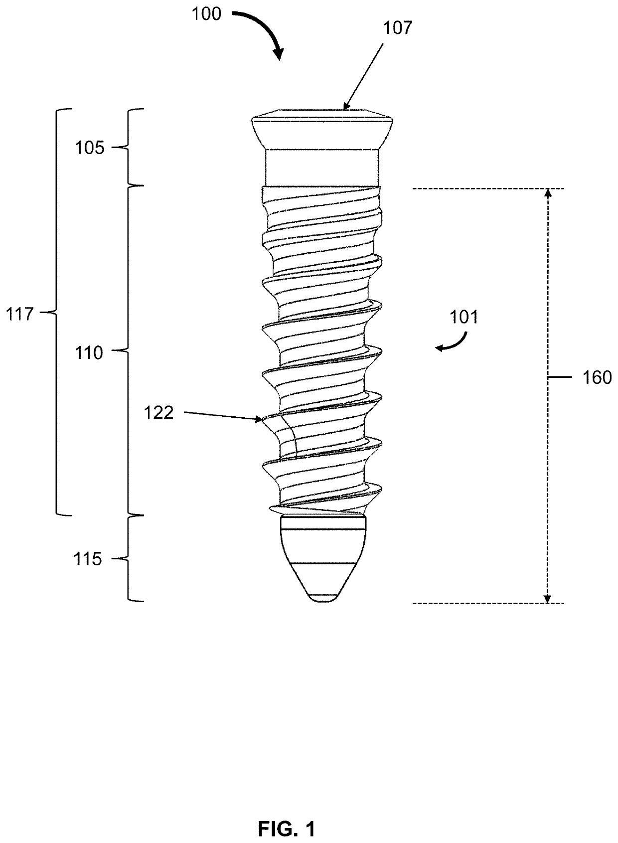
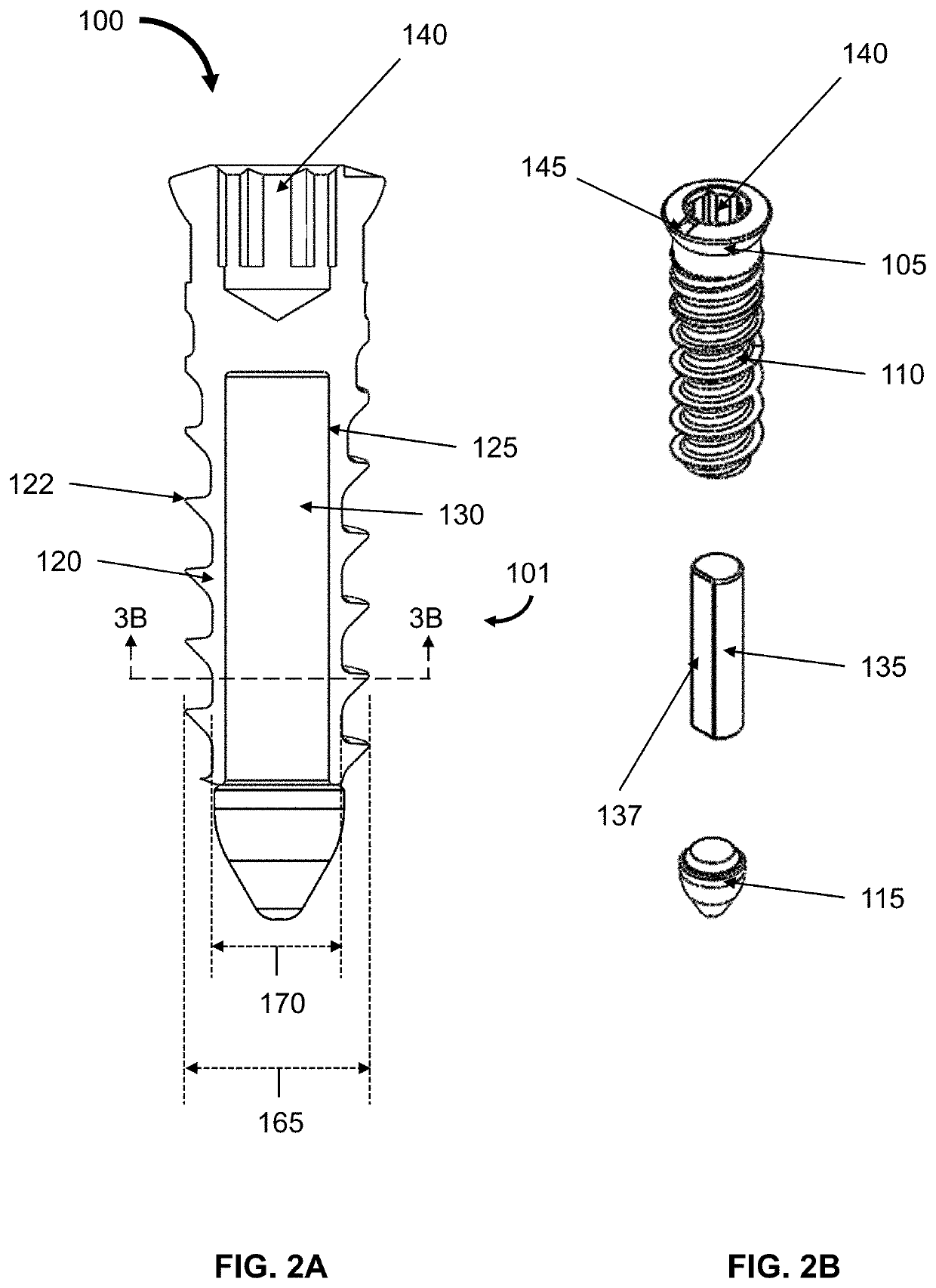
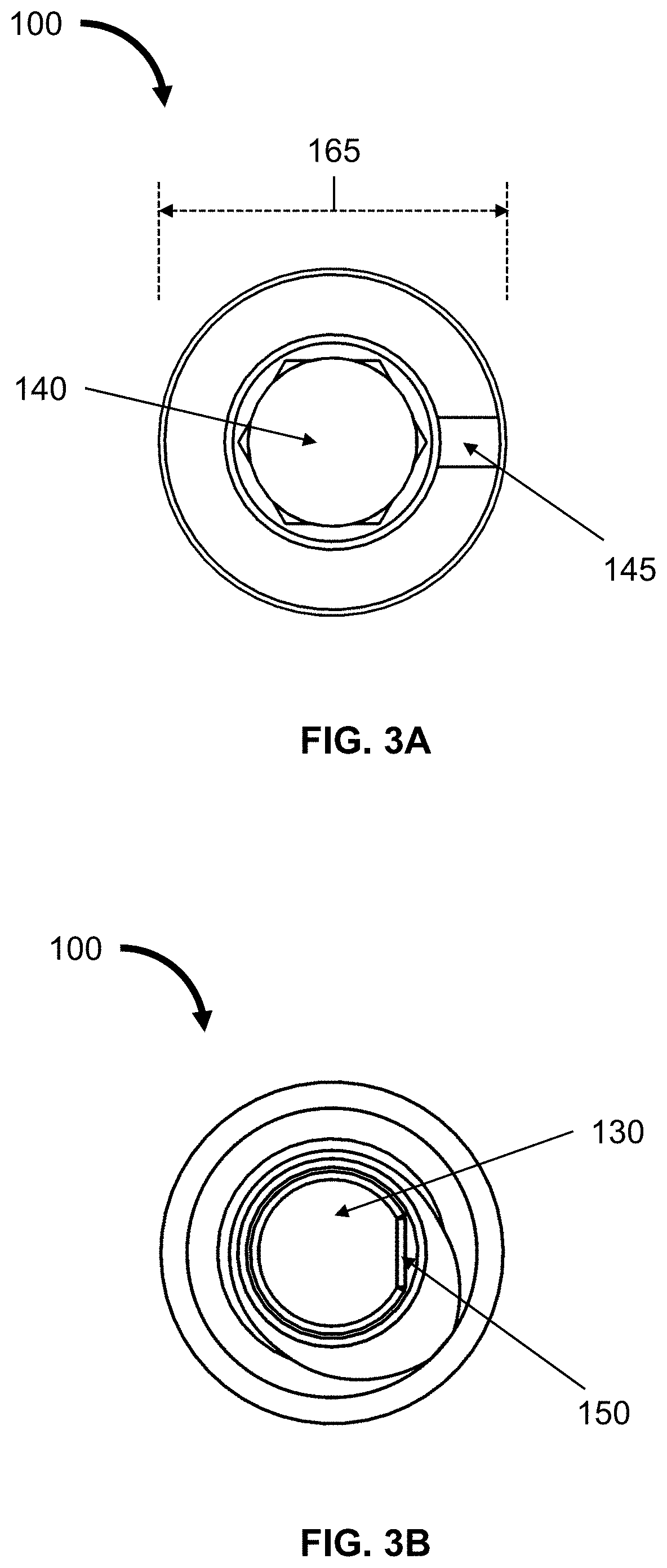
A bone screw comprising a shaft, in which the shaft comprises a bore that is configured to fit a magnet. In addition, a bone plate comprising apertures that can fit the bone screw. The bone plate may be fastened to bone using the bone screws, and the bone screws may be oriented to generate attractive or repulsive forces. Further, a disc-shaped housing that comprises a magnet.

Description

CROSS-REFERENCE TO RELATED APPLICATIONS[0001]This application is a continuation-in-part of U.S. patent application Ser. No. 15 / 677,822, filed on Aug. 15, 2017, which claims the benefit of U.S. Provisional Application Ser. No. 62 / 545,572, filed on Aug. 15, 2017, which are each hereby incorporated by reference in its entirety.BACKGROUND OF THE INVENTION[0002]In vertebrates (including mammals such as humans), bones and connective tissues such as cartilage can break, fracture, or otherwise become damaged due to injury, age, heredity, or combinations thereof. This is particularly true for cartilage and components of the intervertebral disc that can degenerate, resulting in pain and pressure on the spinal cord.[0003]Additional nonsurgical treatments for acute and chronic cervical neck pain, which may be a result of the above, include various traction methods. For example, manual cervical traction can include inflatable neck collars and over-the-door traction devices, as well as physical t...

Claims


Application Information

Patent Timeline
Patent Type & Authority Patents(United States)
IPC IPC(8): A61B17/88A61B17/80A61B34/00A61F2/44A61B17/86A61B17/70A61L31/02A61L31/14A61B17/00A61B17/56A61B17/68
CPCA61L31/022A61B17/866A61B17/8004A61B17/8625A61B34/73A61B17/7059A61B17/864A61L31/14A61B17/8052A61B2017/00858A61B2017/00876A61B2034/733A61B2017/564A61B2017/681A61B2017/00951A61B17/8014A61B17/8866A61B90/92A61B17/8023A61B17/8042
Inventor COOK, STEPHEN D.SALKELD, SAMANTHA L.PATRON, LAURA P.NOLAN, LIAM P.HARRISON, MICHAEL C.
Owner GOMBOC LLC
Learn More