
Refrigerator

Active Publication Date: 2019-02-21
LG ELECTRONICS INC
View PDF0 Cites 2 Cited by
  • Summary
  • Abstract
  • Description
  • Claims
  • Application Information

AI Technical Summary

Benefits of technology

[0040]According to an embodiment of the present invention, it is possible to provide a receiving unit capable of minimizing a space required for installation and a refrigerator including the receiving unit.
[0041]According to an embodiment of the present invention, it is possible to provide a receiving unit provided in a partition wall, configured to isolate storage spaces from each other, so as to provide an additional storage space without reducing a predetermined space for receiving storage objects, and a refrigerator including the receiving unit.
[0042]According to an embodiment of the present invention, it is possible to provide a refrigerator designed to facilitate manipulation of a door for opening and closing a receiving unit and to minimize an amount of space required for manipulation of the door, thereby minimizing a reduction in the amount of storage space in the refrigerator.
[0043]According to an embodiment of the present invention, it is possible to provide a refrigerator designed to provide a door having a restoring force so as

Problems solved by technology

Because the storage space provided in the refrigerator is partitioned by drawers, shelves or the line in consideration of the volume of storage objects, the number or the volume of receiving components (shelves, drawers and the like) capable of being mounted in the storage space having the maximum volume, which is determined according to the capacity of the refrigerator, is inevitably restricted.
However, a change of design in which the number or the volume of drawers and shelves is reduced for installation of a new receiving component ma

Method used


Image

  • Refrigerator
  • Refrigerator
  • Refrigerator

Examples


Example

BEST MODE

[0054]Hereinafter, preferred embodiments of the present invention, which is able to specifically achieve the above objects, will be described with reference to the accompanying drawings.

[0055]Unless otherwise specially indicated, all terms used in the specification are identical to general meanings of the terms understood by a person having ordinary skill in the art. If a term used in the specification conflicts with the general meaning of the term, the meaning should be understood to comply with the definition noted in the specification.

[0056]It should be noted herein that the construction of an apparatus, which will hereinafter be described, and a method of controlling the apparatus are given only for illustrative purposes, and the scope of protection of the invention is not limited thereto. Wherever possible, the same reference numbers will be used throughout the drawings to refer to the same or like parts.

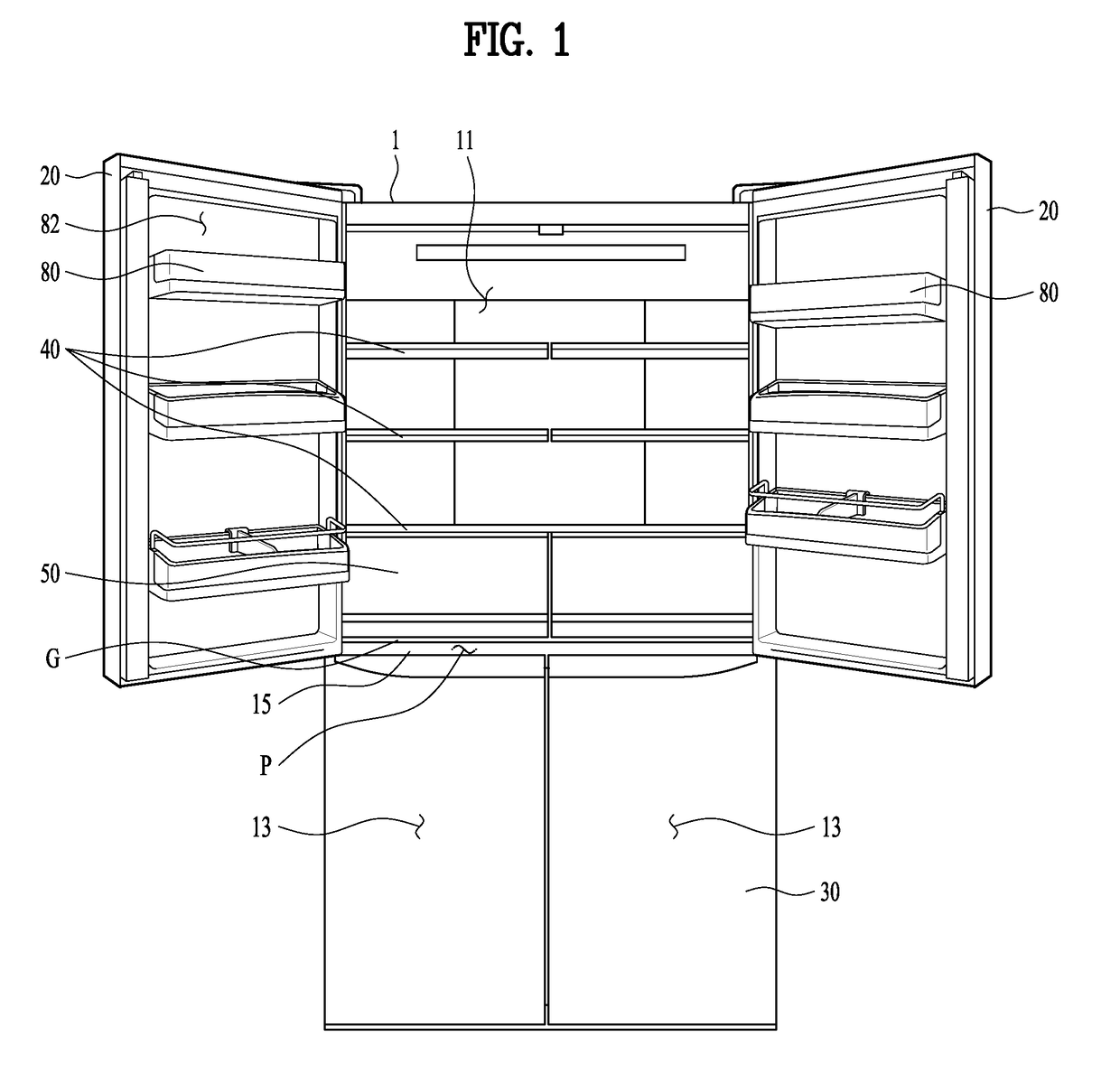
[0057]FIG. 1 is a front view of a refrigerator according to an em...


PUM


Abstract

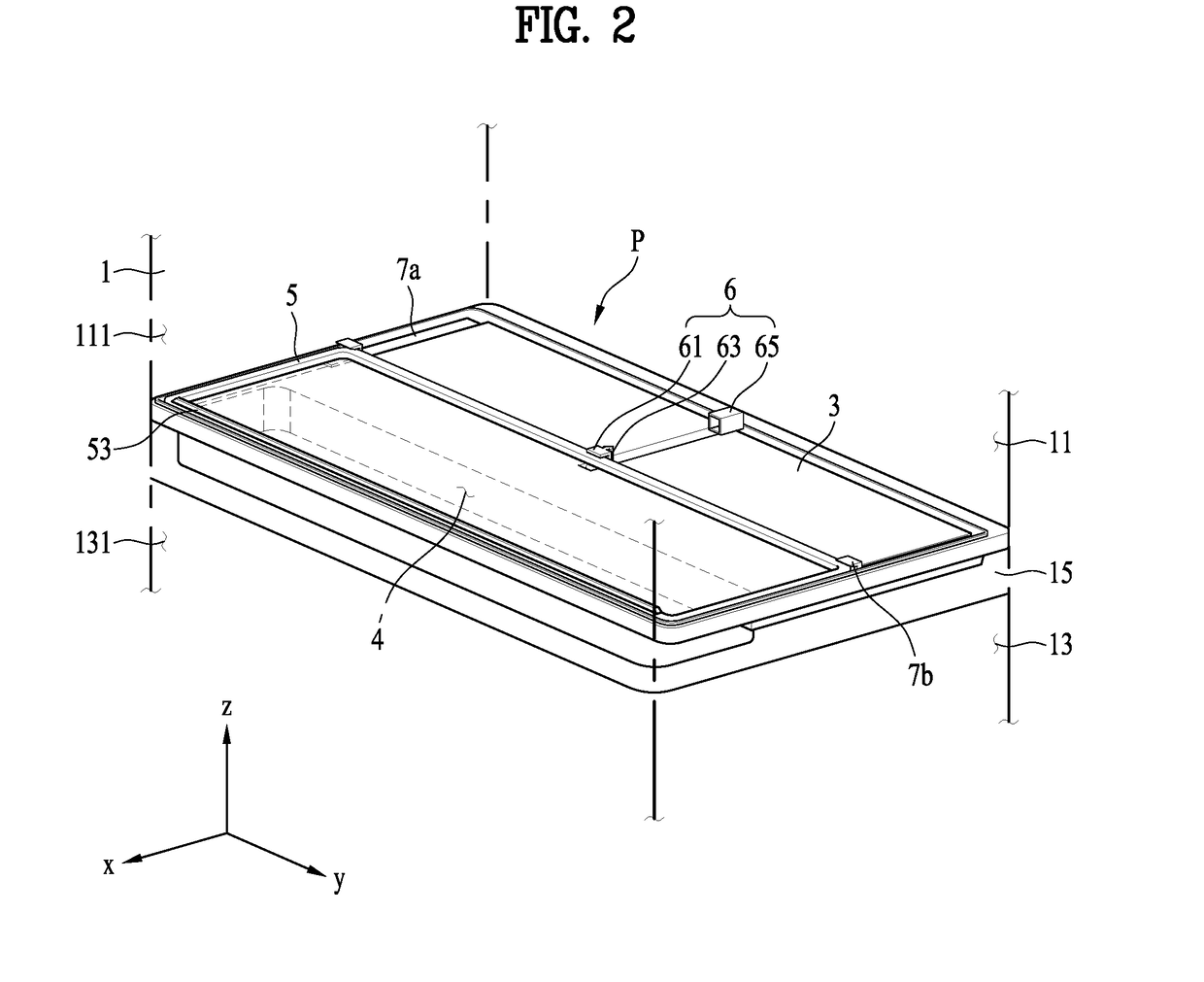
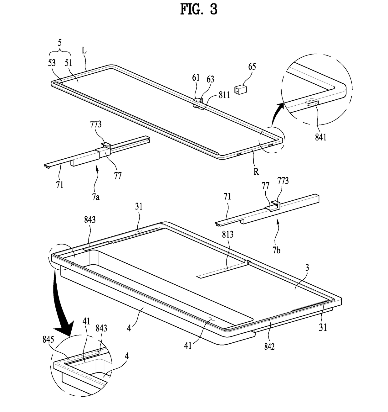
The present invention relates to a refrigerator having a structure of a receptacle apparatus, which enables efficient utilization of a space for storing an object to be refrigerated or an object to be frozen, and a door or a cover which is for opening or closing the receptacle apparatus. Provided is a refrigerator, according to an embodiment of the present invention, comprising: a first storage chamber provided above a cabinet; a second storage chamber positioned below the first storage chamber; a partition wall which is for partitioning the first storage chamber and second storage chamber vertically and of which the upper surface maintains a level position; an accommodation unit recessed downward from the upper side of the partition wall, forming a receptacle space and having an input port, into which an object to be stored is input, formed on the upper part thereof; an accommodation unit door provided so as to be movable in the direction parallel to the upper side of the partition wall and for selectively opening or closing the input port; and a position fixing unit provided on the rear of the accommodation unit door and for restraining the movement of the door when the accommodation unit door moves backward and opens the input port.

Description

TECHNICAL FIELD[0001]The present invention relates to a refrigerator, and more particularly to a receiving unit configured to efficiently utilize space for storing objects to be refrigerated or frozen and structures of a door and a cover for opening and closing the receiving unit.BACKGROUND ART[0002]A refrigerator is an apparatus for storing storage objects (objects to be refrigerated or frozen) received in a storage space in a refrigerated or frozen state through a cycle constituted by compression, condensation, expansion and evaporation of refrigerant. In other words, a conventional refrigerator is provided with a storage space for receiving storage objects and a heat exchange unit for absorbing heat from the air in the storage space so as to maintain the storage objects disposed in the storage space at a temperature lower than the ambient temperature.[0003]Because the volume of the storage space is restricted by the storage capacity set for the refrigerator, designing the storage...

Claims


Application Information

Patent Timeline
IPC IPC(8): F25D23/04F25D11/02F25D23/06F25D25/00F25D25/02E05D15/00
CPCF25D23/04F25D11/02F25D23/069F25D25/005F25D25/02E05D15/00F25D2323/021F25D2323/024E05Y2900/31F25D25/024F25D2400/04E05F5/027E05Y2800/24F25D23/021F25D23/02
Inventor CHOI, DAEJIN
Owner LG ELECTRONICS INC
Learn More