
Packaging member

Inactive Publication Date: 2009-03-12
GUSTIN CHRISTOPHER M
View PDF34 Cites 3 Cited by
  • Summary
  • Abstract
  • Description
  • Claims
  • Application Information

AI Technical Summary

Benefits of technology

[0009]One advantage of the present invention is that adjacent packaging members can fully nest with each other, minimizing the space required for transport.
[0010]Another advantage of the present invention is that the packaging member is inexpensive to manufacture due to savings of material costs.

Problems solved by technology

However, tubular containers are expensive to manufacture and require the product be directed into one end of the container, which is cumbersome, and further requires the “packaging loading area” for the product into the packaging member to be at least twice the length of the product.
In addition, transport of already formed empty tubular containers is costly.

Method used


Image

  • Packaging member
  • Packaging member
  • Packaging member

Examples


Embodiment Construction

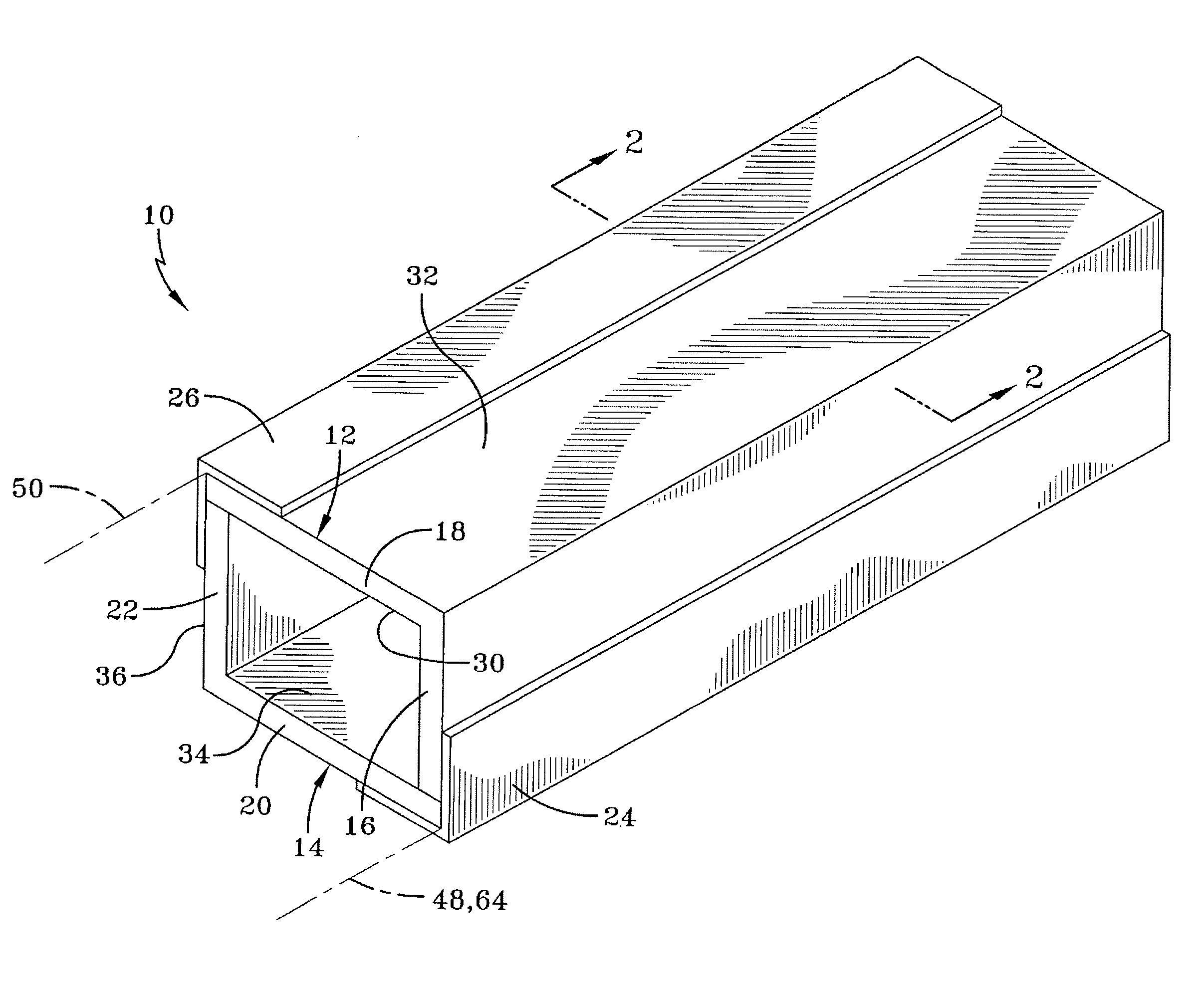
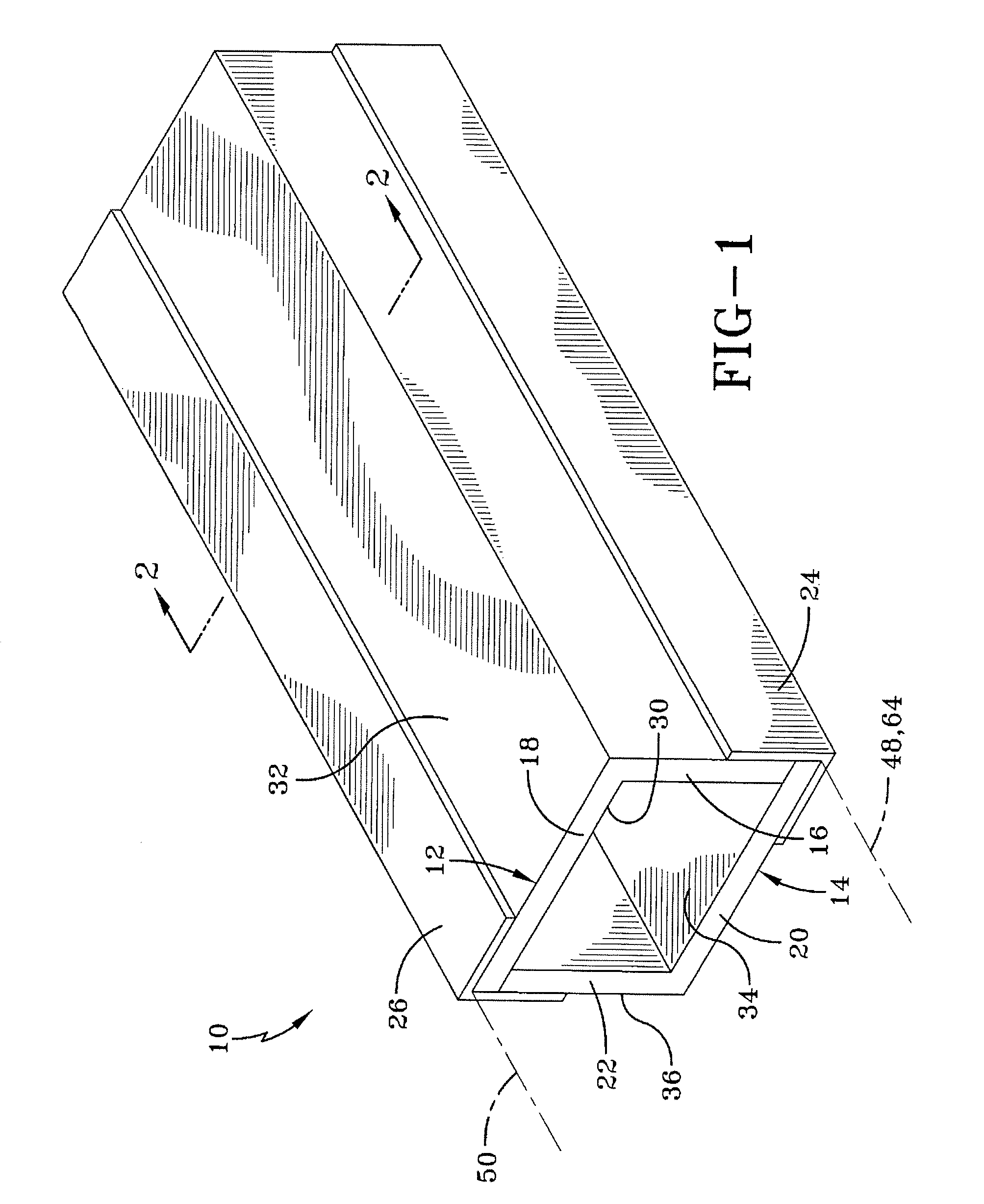
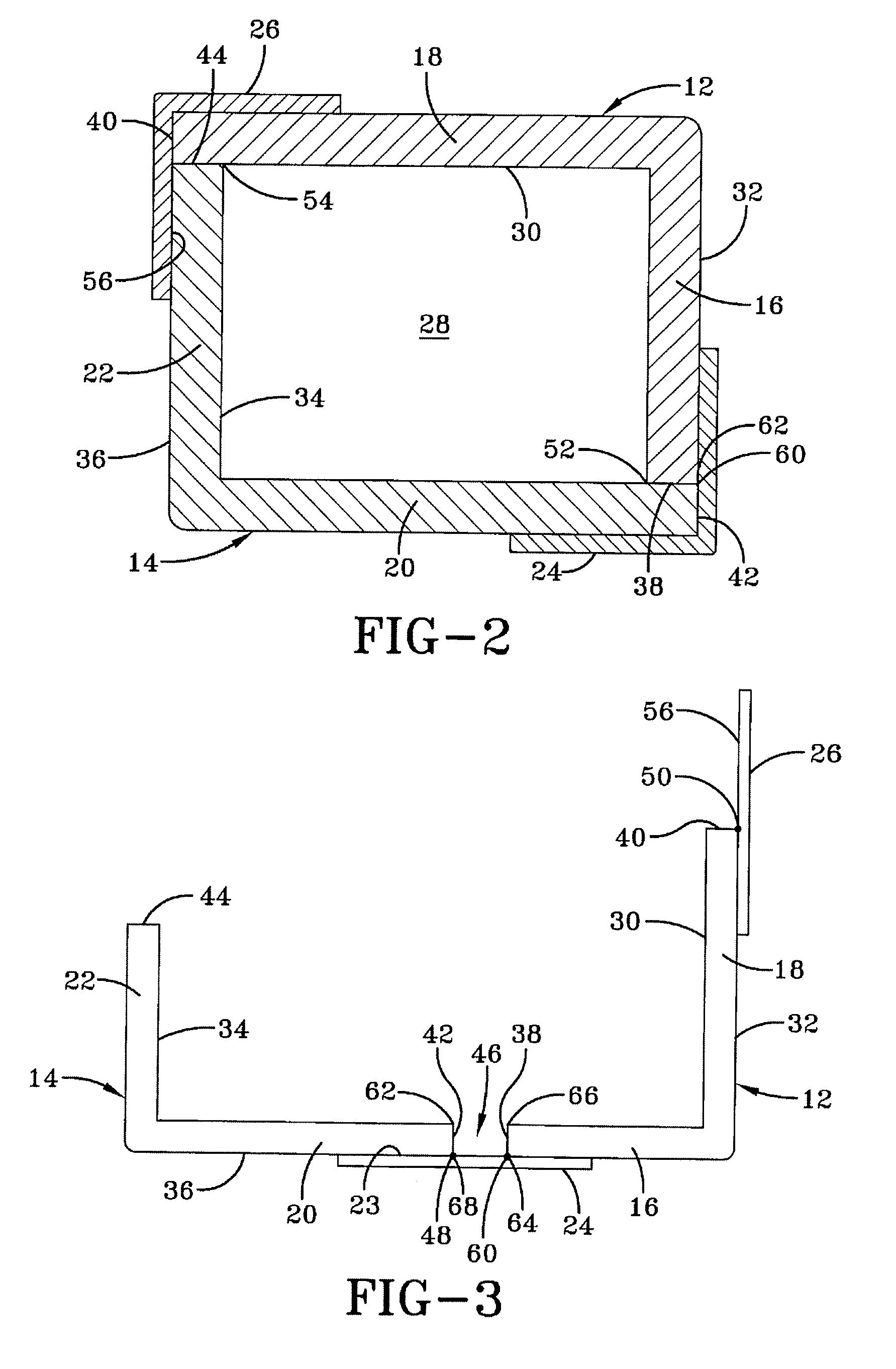
[0037]FIG. 1 illustrates a packaging member 10 for protecting an article (not shown) that is placed inside packaging member 10 prior to transporting the article. Packaging member 10 includes an opposed pair of rigid members 12, 14, commonly referred to as corner posts, angles or L-shaped members. Angles or L-shaped members 12, 14 each have a pair of respective legs 16, 18 and 20, 22. It is to be understood that the legs of L-shaped members can be of identical widths or different widths. Each pair of legs 16, 18 and 20, 22 are substantially perpendicular to one another, are of rigid construction with one another and have an L-shaped cross section along their length. The legs 16, 18 and 20, 22 collectively define the structural sides of packaging member 10 when assembled. Referring to FIGS. 1-3, angle 12 has an inner surface 30, outer surface 32 and legs 16, 18. Angle 14 has an inner surface 34, outer surface 36 and legs 20, 22. In one embodiment, an external member applied to an oute...


PUM


Abstract

A packaging member for protecting an edge of an article includes a member having a first leg and a second leg disposed at a predetermined angle to each other along a junction. At least two material plies are integrally connected along the junction. Each of the at least two material plies define a bend having a first width and a second width, wherein the first width and second width define different magnitudes.

Description

BACKGROUND OF THE INVENTION[0001]The present invention relates generally to packaging members, and more particularly to laminated paperboard packaging members for enclosing a product.[0002]Elongated products, especially those having small cross sectional areas typically require special packaging containers for protection from damage while the products are transported. Tubular containers are well known for this purpose. However, tubular containers are expensive to manufacture and require the product be directed into one end of the container, which is cumbersome, and further requires the “packaging loading area” for the product into the packaging member to be at least twice the length of the product. In addition, transport of already formed empty tubular containers is costly.[0003]Another type of packaging member, typically an angle member, protects the edges of larger articles, such as appliances. It is desirable to reduce the costs of these packaging members without adversely affect...

Claims


Application Information

Patent Timeline
IPC IPC(8): B65D81/05
CPCB65D5/04B65D5/322B65D5/32
Inventor GUSTIN, CHRISTOPHER M.
Owner GUSTIN CHRISTOPHER M
Learn More