Systems, monitor mounts, monitors, docks, racks, modules, belt mounts, couplings and connectors

a monitor and system technology, applied in the field of monitor mounts, can solve the problems of inability to integrate inability to work together and leverage the performance advantages of each type of monitor, and inability to achieve the effect of reducing installation and maintenance costs, maximizing workflow, and minimizing the space required for the system of the present disclosur

Pending Publication Date: 2022-03-10
DRAGERWERK AG
View PDF12 Cites 0 Cited by
  • Summary
  • Abstract
  • Description
  • Claims
  • Application Information

AI Technical Summary

Benefits of technology

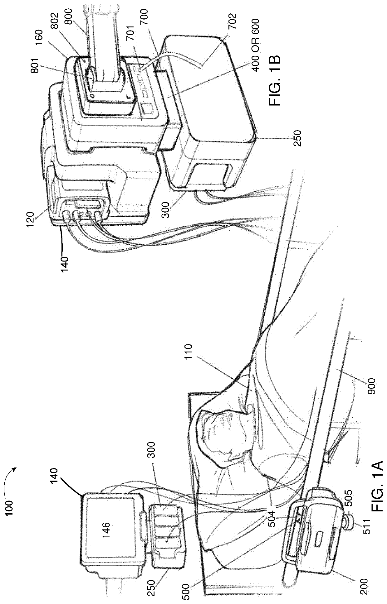
[0034]The system of the present disclosure enables pick and go transport of a patient from one care area of a hospital to another care area of the hospital without having to disconnect the patient from a patient monitor. For example, the system of the present disclosure streamlines workflows by being able to go from bedside to transport in the push of a button. Cables and modules can remain attached to the patient and parameters and alarms can continue to be monitored in real time, while recording data during travel. The system of the present disclosure can also provide seamless wired-to-wireless networking, so surveillance can be continuous. No disconnection or reconnection of leads is required and there are no gaps in monitoring or data acquisition. As a result, all parameters that are monitored at the bedside can continue to be monitored on transport.
[0035]The system of the present disclosure therefore allows monitors to be mixed and matched across different care areas and geographies such that workflow is optimized. The system of the present disclosure also requires fewer mounting points than current systems, thereby reducing installation and maintenance costs. Since the monitor mount and one or more monitors are integrated and consolidated, the space required for the system of the present disclosure is minimized. The system of the present disclosure can be used in dry and wet zones and contributes to an enhanced level of hygiene. According to caregiver preference, the system of the present disclosure can be scaled to the patient's needs—from basic monitoring to using the full range of all of the monitors. To support individual workflow, multiple monitors can be used, for example, to support anesthesiologists, perfusionists, and surgeons if a surgical display controller is used.
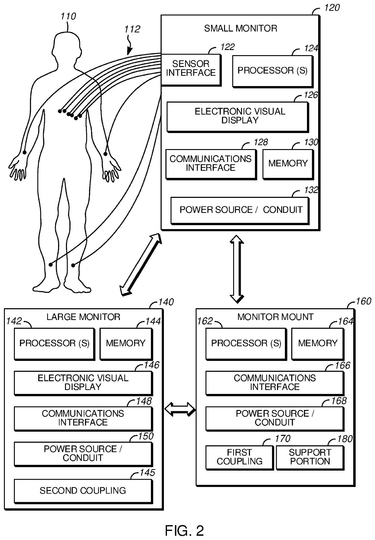
[0036]The system of the present disclosure provides a high acuity care system that improves aesthetics and ergonomics by allowing different caregivers to view the information they need at the same place. The system of the present disclosure can be used as part of a healthcare enterprise solution and can bring comprehensive information to the point of care, while continuously monitoring the patient. For example, the system of the present disclosure can provide access to images, lab results and other clinical data, while displaying real-time vital signs data at the point of care. Furthermore, the performance advantages of differently sized monitors can be combined and leveraged. For example, the portability of a smaller monitor and the increased functionality of a larger monitor can be independently or concurrently capitalized upon.
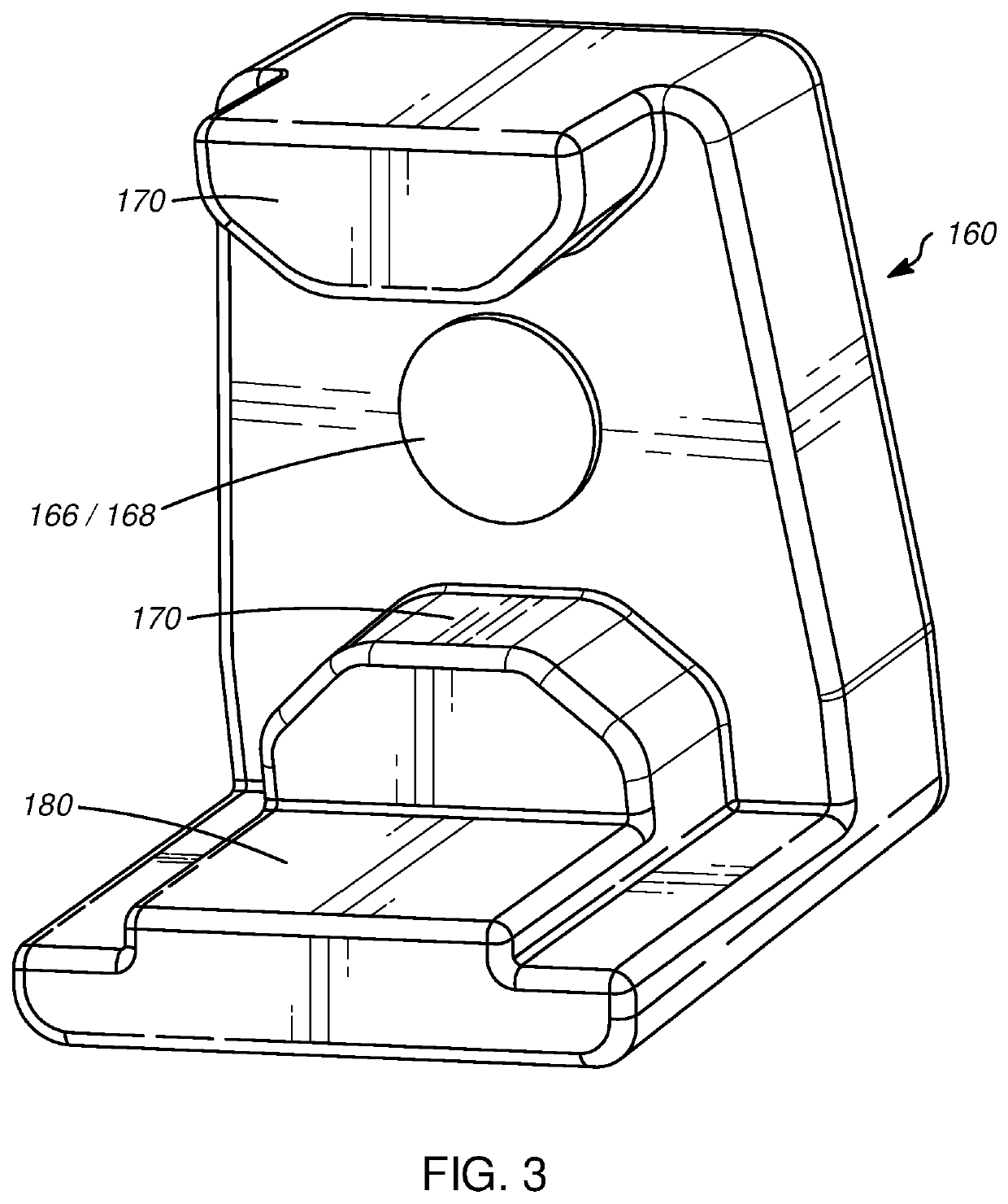
[0037]The subject matter described herein provides many technical advantages. For example, the current subject matter enables the mounting of two monitors having different sizes, shapes, and functionality on a single monitor mount.

Problems solved by technology

Accordingly, such monitors are not interoperable and the performance advantages of each type of monitor cannot be combined and leveraged.
Since such docks have been stationary or fixed (i.e., not mobile or transportable), this can cause gaps in data acquisition.
A drawback associated with this scenario is that each patient monitor needs to be connected to a dedicated cradle or dock which is connected to a central station or HIS enabling transfer of patient data from the respective patient monitor, through the central station or HIS, to a repository of patient data associated with the respective patient.
One reason for this is because many conventional portable patient monitors do not have the ability to record and store patient data on a removable storage medium (e.g., memory card).
A further drawback with the current state of monitors is, when connecting the patient to a different patient monitor, the newly connected patient monitor must query the repository to acquire the patient parameter data that was recently uploaded by the original patient monitor.
The delays associated with the conventional patient parameter data transfer process are not only time consuming and increase the chances of human error associated with manual reconfiguration of patient monitors, but also may result in an interruption in monitoring of the patient.
Such a rectangular shape makes conventional monitors difficult to grip, difficult to clean, and limits the size and shape of batteries stored therein.
In addition, the conventional couplings allow the device to be fastened to the mount in only one orientation, thereby requiring the user to visually confirm the orientation of the device and the mount before fastening, which is time-consuming and burdensome in a hospital setting where rapid treatment and triage are often necessary.
The device and the mount are typically bolted together or otherwise rigidly attached and cannot be separated without the use of specialized tools.
Conventional mounts are difficult to both quickly and rigidly secure to mobile or transportable support structures such as a bed, stretcher, gurney rail, IV pole, ambulance bar, etc. in addition to stationary support structures.
Furthermore, such mounting is time-consuming and burdensome in a hospital setting.
Conventional couplings for a device and a mount require a user to visually confirm the orientation of the device and the monitor mount before fastening, which is time-consuming and burdensome in a hospital setting.
The device and the mount are typically bolted together or otherwise rigidly attached and cannot be separated without the use of specialized tools.
When modules are not secured in the one position in the rack, they usually will fall or drop out of the rack due to gravity.
The modules cannot be mechanically retained by the rack while being electrically disconnected from the housing.
Conventional connectors often have inconspicuous keying and are difficult to mate with corresponding interfaces, particularly in low light or dark conditions.

Method used


Image

  • Systems, monitor mounts, monitors, docks, racks, modules, belt mounts, couplings and connectors
  • Systems, monitor mounts, monitors, docks, racks, modules, belt mounts, couplings and connectors
  • Systems, monitor mounts, monitors, docks, racks, modules, belt mounts, couplings and connectors

Examples


Embodiment Construction

[0172]The following description is made with reference to the accompanying drawings and is provided to assist in a comprehensive understanding of various example embodiments of the present disclosure. The following description includes various details to assist in that understanding, but these are to be regarded as merely examples. Accordingly, those of ordinary skill in the art will recognize that various changes and modifications of the examples described herein can be made without departing from the spirit and scope of the present disclosure. In addition, descriptions of well-known functions and constructions may be omitted for clarity and conciseness.

[0173]The terms and words used in the following description and claims are not limited to the bibliographical meanings, but are merely used to enable a clear and consistent understanding of the present disclosure. Accordingly, it should be apparent to those skilled in the art that the following description of the present disclosure ...


PUM


Abstract

A connector system includes a male connecter including a male housing defining a recess and a plurality of pins arranged within the recess; and a female connector including a female housing configured to be insertable into the recess of the male housing. The female housing includes: front and back portions; a pair of longitudinal sides that extend from the front portion to the back portion; a planar side that extends from the front portion to the back portion, the planar side connecting first ends of the pair of longitudinal sides; a rounded side that extends from the front portion to the back portion, the rounded side connecting second ends of the pair of longitudinal sides; a front surface defined at the front portion by the pair of longitudinal sides, the planar side, and the rounded side; and a plurality of sockets formed at the front surface.

Description

FIELD OF THE DISCLOSURE[0001]The present disclosure generally relates to: a monitor mount that is able to receive differently sized monitors, and more specifically, to a monitor mount that enables data transfer between the monitor mount and the monitors received thereby; a dock that is able to receive a device, and more specifically, to a dock that enables data transfer between the dock and the device received thereby; a first monitor that is able to interface with a second monitor and the monitor mount; a coupling including a rotatable top piece that is able to quickly and easily secure a device to a mount; a belt mount that is able to quickly and rigidly secure a device to a support structure; a coupling including leaves that are able to quickly and easily secure a device to a mount; a rack that is able to secure a module in one of two different positions therein; a connector that is able to electrically connect two devices and provides an electrical connection that can be simply ...

Claims


Application Information

Patent Timeline
Patent Type & Authority Applications(United States)
IPC IPC(8): H01R13/64H01R13/6583H01R33/76
CPCH01R13/64H01R24/20H01R33/7657H01R13/6583H01R13/6456H01R13/005H01R2107/00H01R2201/12H01R24/68A61B2562/182A61B2562/227A61B2562/228A61B5/7425A61B5/7445A61B5/02A61B5/0205A61B5/002A61B2505/01A61B2560/0431A61B2560/045A61N1/3904A61G7/05H01R24/28H01R33/765
Inventor PROVENCHER, ANDREW T.ESLAVA, JUAN P.MAGILL, JOHN C.HENNINGS, NOAHLUND, PETER A.SWYST, THOMASAISTON, CHRISTOPHERHENNINGS, ZACHARY K.RANE, RAJESH S.BEINART, DANIEL
Owner DRAGERWERK AG
Why Eureka
Try Eureka