
Lighting control data identification

a technology of control data and identification, applied in the direction of data switching network, multi-programming arrangement, instruments, etc., to achieve the effect of fast scene recall

Active Publication Date: 2019-02-21
SIGNIFY HLDG BV
View PDF8 Cites 0 Cited by
  • Summary
  • Abstract
  • Description
  • Claims
  • Application Information

AI Technical Summary

Benefits of technology

This patent describes a computer-implemented method for controlling lighting in a networked lighting system. The system stores lighting control data in various nodes, such as a lighting node or hub, which can be accessed by other nodes in the system. The data can include information about the lighting output for specific scenes or rules for setting a scene at a certain time of day. When a new scene is needed, the system can quickly recall the appropriate data without having to connect a computer device to each individual lamp. This saves time and alleviates the need for complex lighting settings.

Problems solved by technology

When a user sets an alarm causing a bedroom light to turn on at a certain time, it is undesirable if this requires the application for setting the alarm to be running on the smart phone at the time the alarm is set to go off.
When a user can only recall that scene using the specific phone the scene is stored on, this is undesirable in view of, for example, other users of the same networked lighting system lacking access to that same scene via their own smart phones.

Method used


Image

  • Lighting control data identification
  • Lighting control data identification
  • Lighting control data identification

Examples


Embodiment Construction

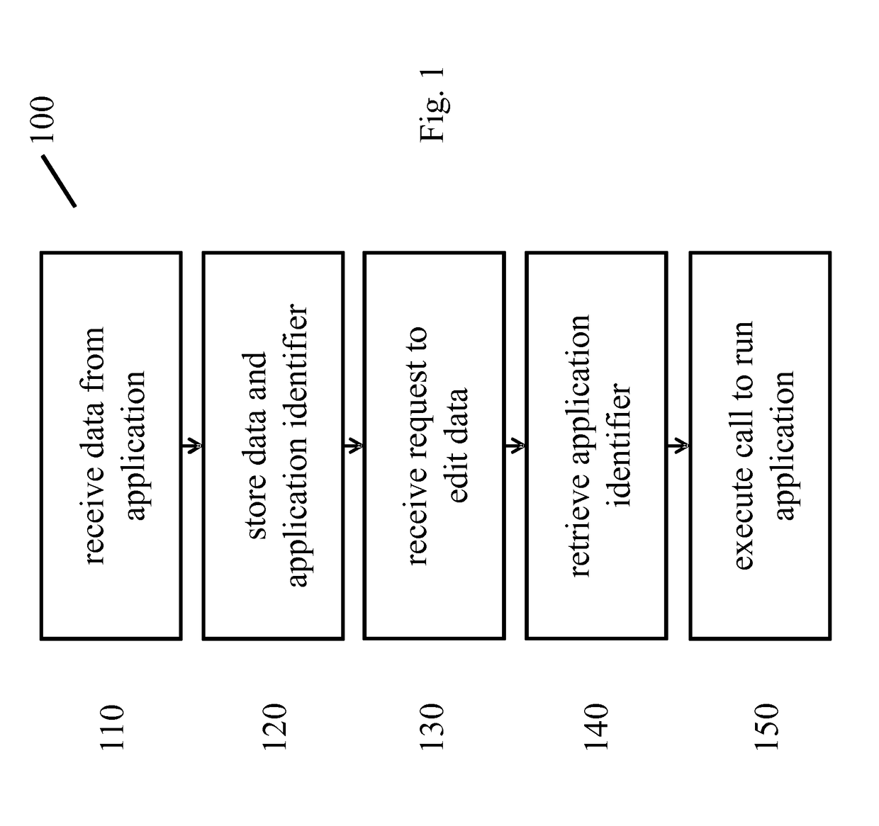
[0028]In FIG. 1 an embodiment of a computer implemented method 100 for controlling, based on lighting control data, a networked lighting system is shown. The method comprises:[0029]receiving 110 the lighting control data from an application running on a first computer device,[0030]storing 120 in a node of the networked lighting system a data set, the data set based on the lighting control data and comprising identification data identifying the application which the lighting control data was created with,[0031]receiving 130 from an application running on a second computer device an input indicating an editing of the lighting control data,[0032]retrieving 140 the identification data comprised in the data set which is based on the lighting control data, and[0033]executing 150 an application call based on the retrieved identification data, such that the second computer device runs the application which the lighting control data was created with.

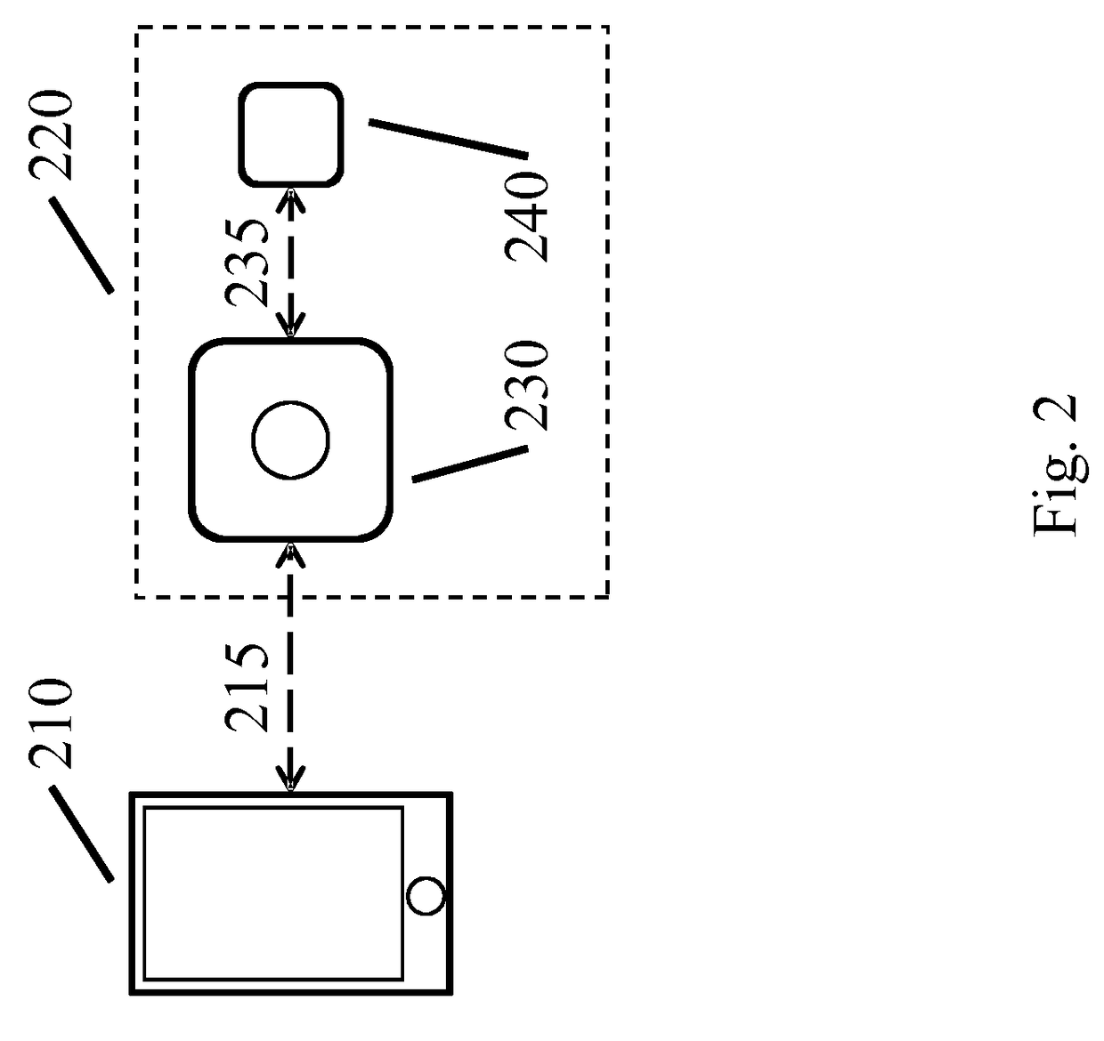
[0034]In FIG. 2 an example of a networked ...


PUM


Abstract

A networked lighting system is provided which stores, e.g. in a lighting controller node, lighting control data such as scenes or rules based on receiving such data from an application running on a first computer device. An identification of the application which lighting control data was received from is stored alongside this data. When an input is received by (a node in) the networked lighting system from an application running on a second computer device indicating that the lighting control data is to be edited, an application call is executed such that the application the lighting control data was received from is run on this second computer device.

Description

FIELD OF THE INVENTION[0001]The invention generally relates to a method for controlling a networked lighting system and in particular to editing control data for controlling such a networked lighting system. The invention further relates to a computer program product for performing the method, to a node in a networked lighting system and to a system.BACKGROUND OF THE INVENTION[0002]Networked lighting devices offer advanced control options, such as scene setting and rule based control. A user can access such control options via a remote control device, such as a smart phone. Scene data can be stored on the smart phone and / or on a node in a networked lighting system, such as in a memory of the networked lighting device. Storing scene data on a node in the lighting system, such as on a networked lighting device, allows a scene recall to be performed without having access to the application that was used to create the scene.[0003]From US 2011 / 140832 A1 it is known to have a system with ...

Claims


Application Information

Patent Timeline
IPC IPC(8): H04L29/08H05B37/02H04L12/28G06F8/60G06F9/54
CPCH04L67/125H05B37/0245H04L12/2816H04L12/2832H04L67/34G06F8/60G06F9/547H04L12/282H04L2012/2841H04L2012/285H05B47/175
Inventor MAGIELSE, REMCOCHEN, BINGZHOU
Owner SIGNIFY HLDG BV
Learn More