Lighting control data identification

a technology of control data and identification, applied in the field of lighting control data identification, to achieve the effect of fast scene recall

Active Publication Date: 2022-01-25
SIGNIFY HLDG BV
View PDF19 Cites 0 Cited by
  • Summary
  • Abstract
  • Description
  • Claims
  • Application Information

AI Technical Summary

Benefits of technology

[0010]The computer implemented method allows lighting control data to be stored in the networked lighting system, such as in a lighting node or a hub, bridge or controller node. This is beneficial as it supports the lighting control data to be accessed by other nodes in the system. For example, if the lighting control data is a scene describing light output of one or more lighting nodes, then the scene can be recalled not only by the computer device running the application that was used to create it. It can then, continuing the example, be recalled by a properly configured wall switch node in the networked lighting system. As a further example, if the lighting control data is a rule related to setting a scene at a specific time of day, then the scene can be recalled at the appropriate time by executing the rule by a node in the networked lighting system. This can alleviate the need for the computer device, such as a smart phone, running the application that has set the rule to be connected to the networked lighting system when the rule is triggered to set the scene.
[0012]The data set is stored in a node of the networked lighting system. For example, the data set can be stored in a lighting node or a hub, bridge or controller node of the networked lighting system. Although the data set will be stored in at least one node, the data set or different versions of the data set can be stored in multiple nodes. For example, the romantic scene setting two out of three lamps to red can be stored in the two lighting nodes that emit light to contribute to this specific scene. The data stored in each of these two lighting nodes then relates to the light output of that specific node for that specific scene. When the romantic scene is to be set in the networked lighting system, a scene command can then be sent to all nodes in the networked lighting system and those nodes that have a role in creating the scene can in their own local memory look up what their light output should be in that scene. This can be beneficial as it allows for fast scene recall, as it is not necessary to address individual lamps and / or transmit specific light settings when a scene is recalled.

Problems solved by technology

When a user sets an alarm causing a bedroom light to turn on at a certain time, it is undesirable if this requires the application for setting the alarm to be running on the smart phone at the time the alarm is set to go off.
When a user can only recall that scene using the specific phone the scene is stored on, this is undesirable in view of, for example, other users of the same networked lighting system lacking access to that same scene via their own smart phones.

Method used


Image

  • Lighting control data identification
  • Lighting control data identification
  • Lighting control data identification

Examples


Embodiment Construction

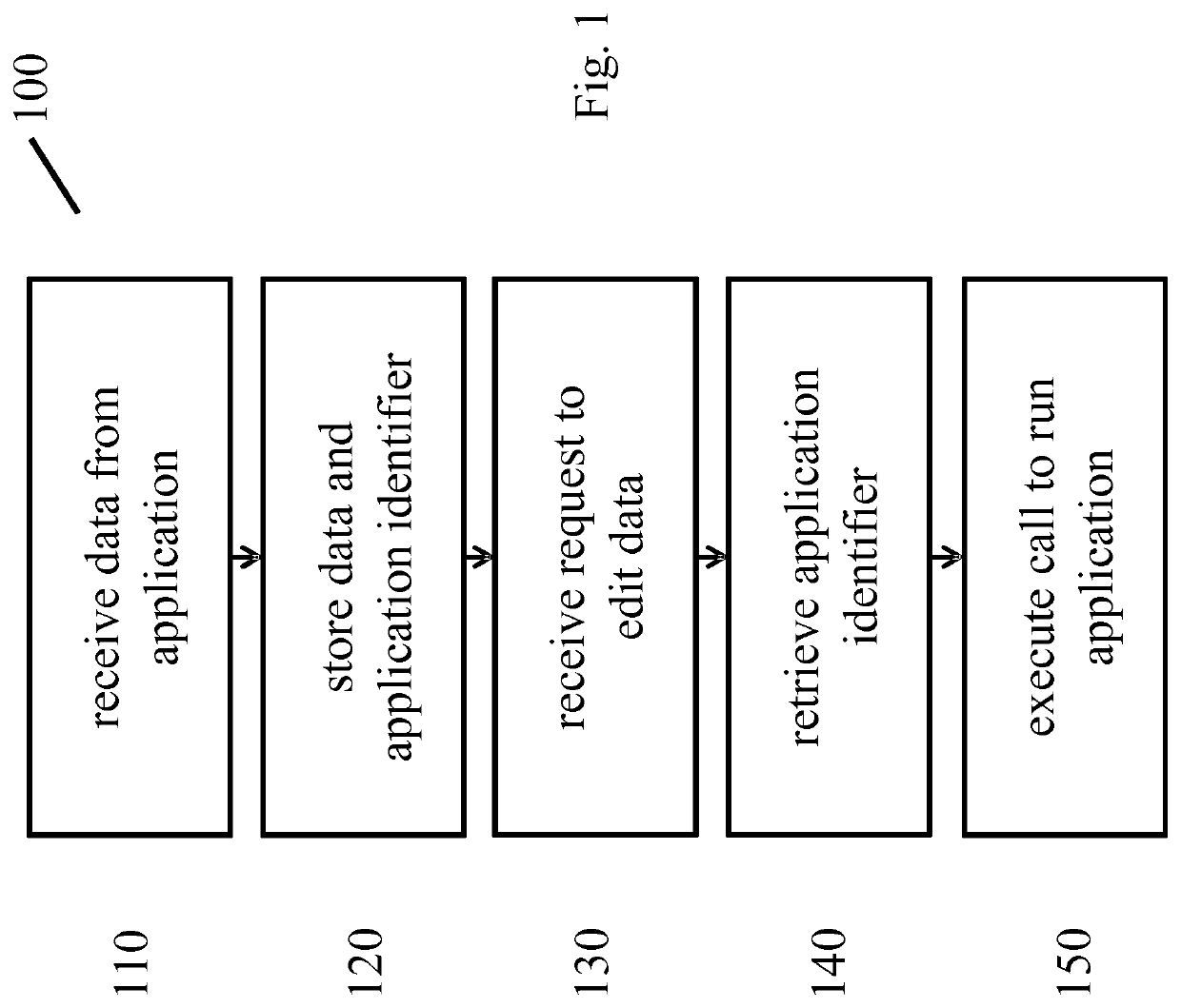
[0029]In FIG. 1 an embodiment of a computer implemented method 100 for controlling, based on lighting control data, a networked lighting system is shown. The method comprises:[0030]receiving 110 the lighting control data from an application running on a first computer device,[0031]storing 120 in a node of the networked lighting system a data set, the data set based on the lighting control data and comprising identification data identifying the application which the lighting control data was created with,[0032]receiving 130 from an application running on a second computer device an input indicating an editing of the lighting control data,[0033]retrieving 140 the identification data comprised in the data set which is based on the lighting control data, and[0034]executing 150 an application call based on the retrieved identification data, such that the second computer device runs the application which the lighting control data was created with.

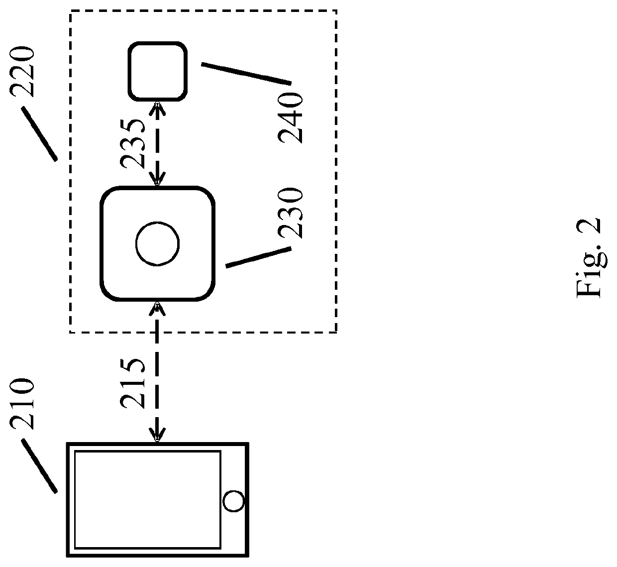
[0035]In FIG. 2 an example of a networked ...


PUM


Abstract

A networked lighting system is provided which stores, e.g. in a lighting controller node, lighting control data such as scenes or rules based on receiving such data from an application running on a first computer device. An identification of the application which lighting control data was received from is stored alongside this data. When an input is received by (a node in) the networked lighting system from an application running on a second computer device indicating that the lighting control data is to be edited, an application call is executed such that the application the lighting control data was received from is run on this second computer device.

Description

CROSS-REFERENCE TO PRIOR APPLICATIONS[0001]This application is the U.S. National Phase application under 35 U.S.C. § 371 of International Application No. PCT / EP2017 / 052698, filed on Feb. 8, 2017, which claims the benefit of International Application No. PCT / CN2016 / 073761, filed on Feb. 14, 2016 and European Patent Application No. 16163627.9, filed on Apr. 4, 2016. These applications are hereby incorporated by reference herein.FIELD OF THE INVENTION[0002]The invention generally relates to a method for controlling a networked lighting system and in particular to editing control data for controlling such a networked lighting system. The invention further relates to a computer program product for performing the method, to a node in a networked lighting system and to a system.BACKGROUND OF THE INVENTION[0003]Networked lighting devices offer advanced control options, such as scene setting and rule based control. A user can access such control options via a remote control device, such as a...

Claims


Application Information

Patent Timeline
Patent Type & Authority Patents(United States)
IPC IPC(8): H04L29/08G06F8/60H04L12/28H05B47/175G06F9/54
CPCH04L67/125G06F8/60G06F9/547H04L12/282H04L12/2816H04L12/2832H04L67/34H05B47/175H04L2012/285H04L2012/2841
Inventor MAGIELSE, REMCOCHEN, BINGZHOU
Owner SIGNIFY HLDG BV
Why Eureka
Try Eureka