Tab for optical connector

a technology for optical connectors and tabs, applied in the field of tabs for optical connectors, can solve the problems of affecting the workability affecting the work efficiency of optical light guides, and laborious and large amounts of tim

Active Publication Date: 2019-03-14
SANWA DENKI KOGYO KK
View PDF0 Cites 7 Cited by
  • Summary
  • Abstract
  • Description
  • Claims
  • Application Information

AI Technical Summary

Benefits of technology

[0052]This allows firm fixation and holding of the multi-core optical fiber cord without loosely hanging the rear end of the multi-core optical fiber cord at the time of the attachment of the tab.

Problems solved by technology

Recently, as shown in FIG. 16, under the circumstances where the densification of a communication system in the various data centers has become essential, insertion of the plug body 1 into the adaptor 21 by inserting a finger one by one or a pulling operation (disengaging operation) takes troublesome labor and great amounts of time, and therefore makes workability thereof very worse.

Method used


Image

  • Tab for optical connector
  • Tab for optical connector
  • Tab for optical connector

Examples


Embodiment Construction

[0070]Hereinafter, a description will be given in detail of an embodiment of a tab for optical connector according to the present invention with reference to the accompanying drawings.

[0071]

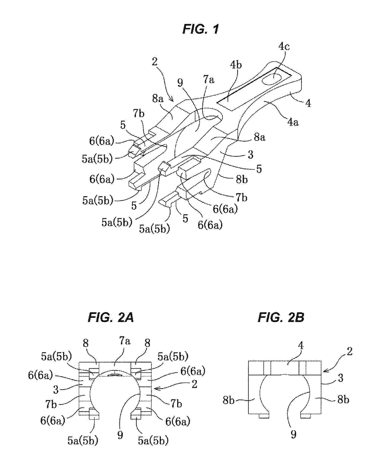
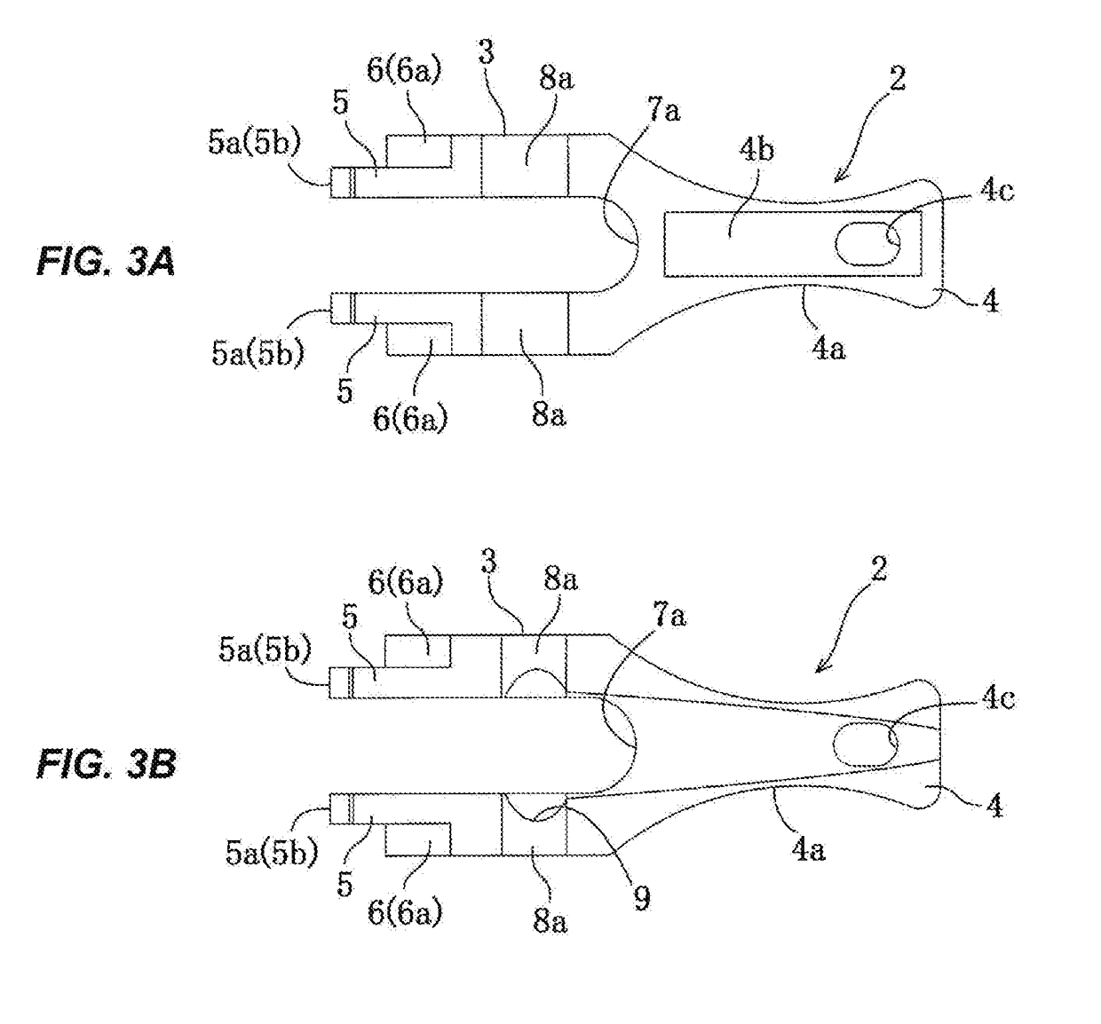
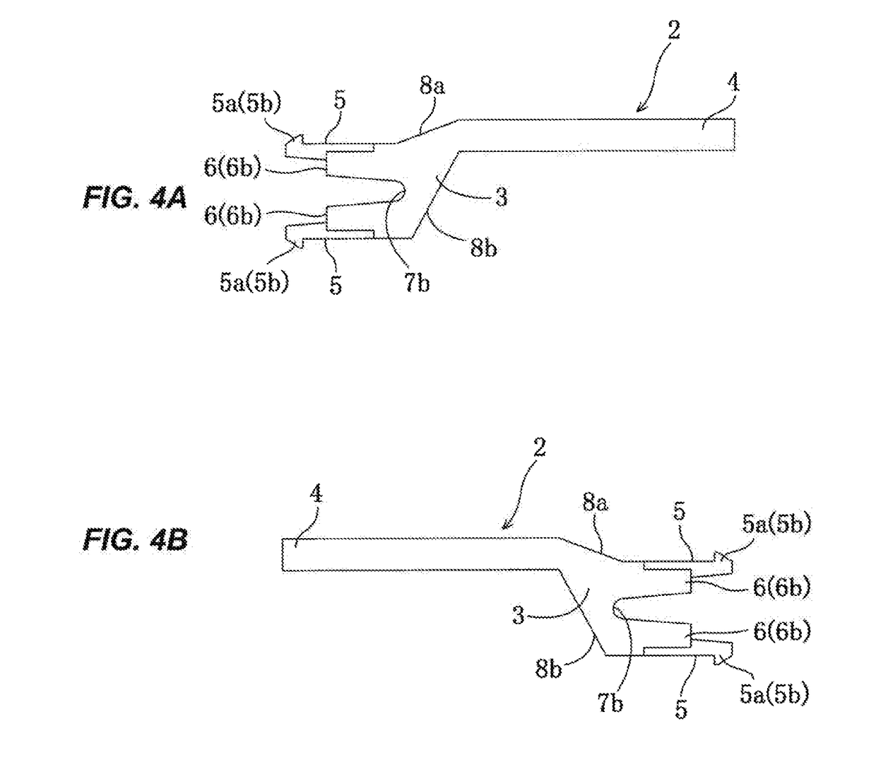
[0072]As shown in FIGS. 1-6, a tab for optical adaptor 2 (hereinafter, referred to as a tab 2) according to the present invention includes operating member 3 which is provided at its tip a plurality of arms 5 (at least four in total) respectively detachably attached and held in a plurality of engaging holes 13a (see FIGS. 5A, 5B and 6) formed at the rear end of a coupling 13 of a plug body 1, and gripping member 4 which is folded and extendingly provided in a substantially chevron shape from the rear end of the operating member 3.

[0073]As shown in FIGS. 1-4A and 4B, the gripping member 4 is formed into a thin sheet finger nipping part 4a whose both left and right sides are curved inwardly. The gripping member 4 includes at its upper surface a seal sticking part 4b and a string inserting hole 4c f...


PUM


Abstract

Provided is a tab (2) including operating member (3) which is provided with an engaging part (5a) at a tip of a plurality of arms (5) so as to detachably attach and hold in each of a plurality of engaging holes (13a) formed at the rear end of a coupling (13), and gripping member (4) which is extendingly provided from the back of the operating member (3), wherein the coupling (13) advances and retreats 3 with respect to a housing (18) by an operation of the operating member (3) in association with the advance and retreat of the gripping member (4), and forward pressing or backward pressing of the plug body (1) is released.

Description

TECHNICAL FIELD[0001]The present invention relates to a tab for optical connector suitable for disengageably attaching a plug body of a MPO type push-pull system optical connector plug (hereinafter, referred to as a plug body) to be mainly connected to an optical connector adaptor (hereinafter, referred to as an adaptor).BACKGROUND ART[0002]In view of the improvement of connection workability of an optical connector ferrule, it has been recently provided a so-called MPO connector (optical connector having a structure in which a multi-core connector ferrule, which is stipulated in the JIS-C5982 standard etc., is received within a plastic housing).[0003]Conventionally, as shown in FIGS. 17A and 17B to be described later, the MPO type plug body 1 receives at the end (front end) of a sleeve-like housing 18 a ferrule 12 which is fitted to a head of a multi-core optical fiber cord FT. Within the housing 18, there is provided a spring 15 which elastically urges the ferrule 12 toward the fr...

Claims


Application Information

Patent Timeline
Patent Type & Authority Applications(United States)
IPC IPC(8): G02B6/38
CPCG02B6/3898G02B6/3821G02B6/3825G02B6/3831G02B6/3869G02B6/3885G02B6/3893
Inventor WATANABE, YASUHIRO
Owner SANWA DENKI KOGYO KK
Why Eureka
Try Eureka