Hook Device

a technology of elastic cords and hooks, which is applied in the direction of hook fasteners, fastening means, domestic applications, etc., can solve the problems of serious injury, cumbersome use of such tie-downs, and inability to attach to sockets or other relatively inaccessible attachment points, so as to improve user control and foster safe operation.

Inactive Publication Date: 2019-03-21
B ERICKSON MFG
View PDF2 Cites 0 Cited by
  • Summary
  • Abstract
  • Description
  • Claims
  • Application Information

AI Technical Summary

Benefits of technology

[0012]The disclosed loop is desirably longitudinally offset from hook (and optionally latitudinally. That is, the hook protrudes out (relative to the location of the end of the stretchable cord) beyond the loop so the hook is in no way impeded by the loop. The loop is generally integrated with a wire metal hook end and is used to pull or stretch a bungee cord toward a location where the hook will be attached. The loop improves user control and fosters safe operation. The loop also provides an alternate location for securing the same bungee cord opposite hook end or the hook of another bungee cord. The entire hook and loop piece is generally made from a single, unbroken length of steel wire, but alternate assembly and manufacturing arrangements are contemplated as well. For instance, separate wire or metal pieces may be welded into the disclosed hook and loop arrangement to make what is, in effect, a continuous, unbroken length of material.

Problems solved by technology

Safety problems in the use of such tie-downs have often been noted.
The loose hook flying back toward the user, or away toward a bystander, can cause serious injury.
Alternate grasping means for such a hook have been proposed both for safety and for ease of use, but the proposed solutions are either cumbersome, relatively fragile, relatively expensive to make, or incapable of attachment in socketed or other relatively inaccessible attachment points.
A loopless hook is difficult to attach to either another hook at the opposite end of the same bungee cord or to a hook of another bungee cord.

Method used


Image

  • Hook Device
  • Hook Device
  • Hook Device

Examples


Embodiment Construction

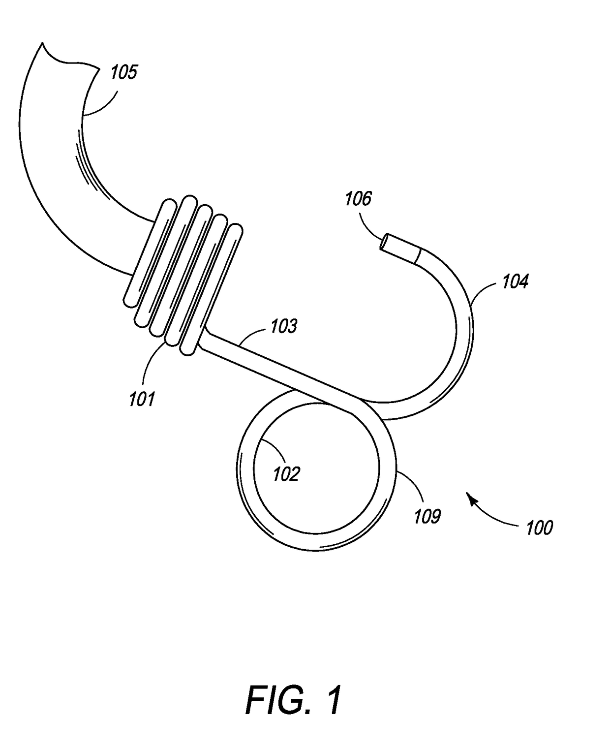
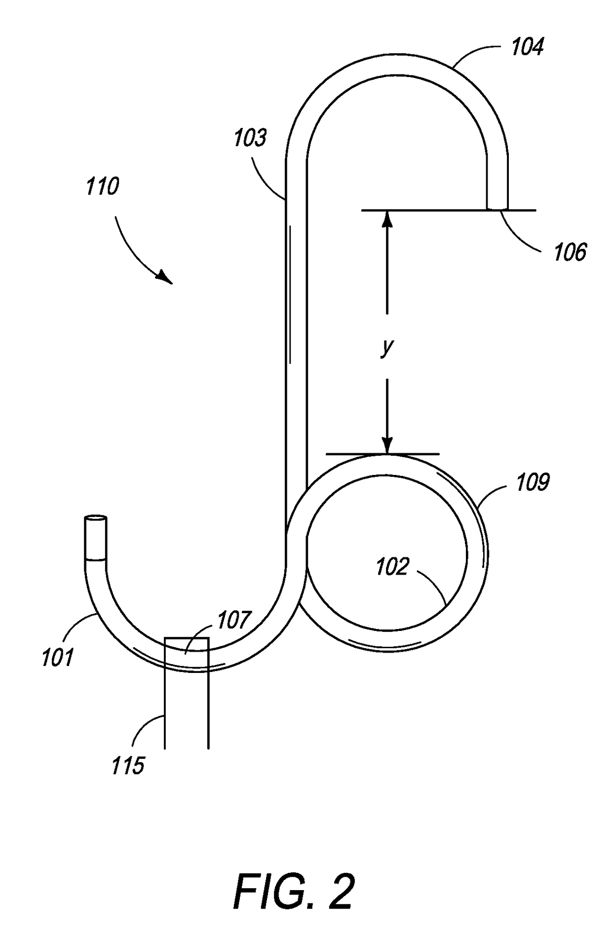
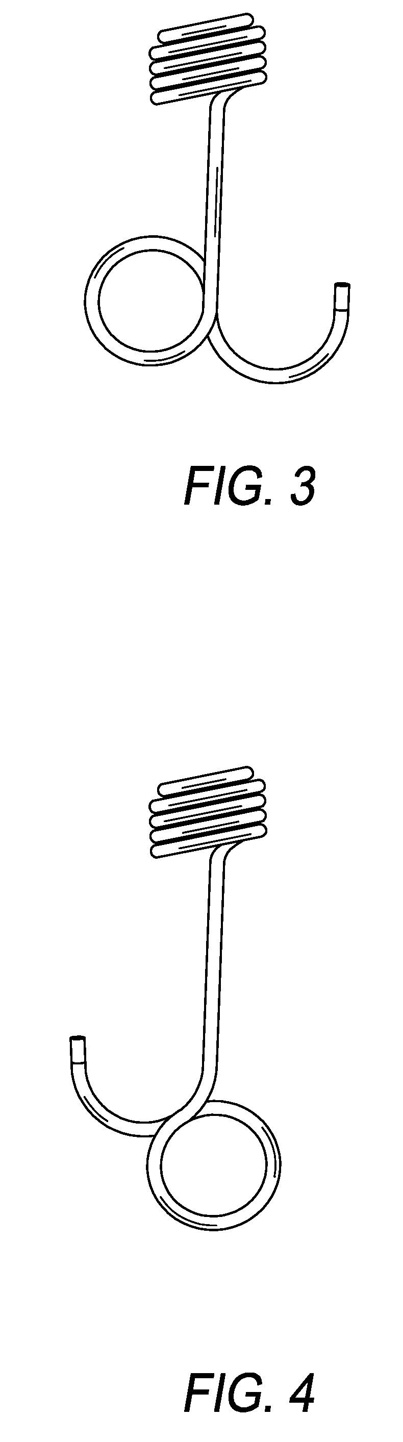
[0031]Turning now to the drawings, the invention will be described in preferred embodiments by reference to the numerals of the drawing figures wherein like numbers indicate like parts.

[0032]As used throughout this specification, the term ‘bungee cord’ shall have its plain and ordinary meaning, and may also include any elastic cord (which may be composed of one or more elastic strands, and may be covered with a sheath) which has a hook device on one end or separate hooks on each end. The elastic cord may comprise rubber or any other elastic material. Without limitation, the elastic cord may be an ethylene propylene diene monomer (“EPDM”) rubber strap.

[0033]A metal hook for a bungee cord is disclosed. One or more metal hooks may be attached to an elastic cord to form a bungee cord before the resulting bungee cord is sold to consumers. Alternatively the metal hook may be manufactured and sold apart from an elastic cord. The metal hook can be made with any metal capable of being stretc...


PUM


Abstract

An elastic cord terminating in a pair of hook devices, each hook device made from a continuous length of wire. The continuous length of wire at one end has a hook bend having a hook tip, and at the other end a cord attachment. The hook bend and the cord attachment are separated by a shank length of the continuous wire into which there is bent a closed finger loop. The finger loop has a hook proximate surface that is separated longitudinally from the hook tip and toward the cord attachment by a selectable clearance distance.

Description

CROSS REFERENCE TO RELATED APPLICATIONS[0001]This application is a Continuation of U.S. patent application Ser. No. 14 / 737276 filed Jun. 11, 2015 which is a Continuation-in-Part of U.S. patent application Ser. No. 14 / 066,642 filed Sep. 29, 2013 which is a Continuation of U.S. patent application Ser. No. 13 / 787,131 filed 3 / 6 / 13 which is a Continuation-in-Part of Ser. No. 13 / 589,455 filed Aug. 20, 2012.TECHNICAL FIELD[0002]The disclosure relates to the field of tie-down and fastening devices; more particularly to an elastic cord with hooks.BACKGROUND[0003]Elastic cords with hooks are widely used for tying down articles or releasably attaching them to various carriers, surfaces and cargo beds. The conventional arrangement is usually referred to as a bungee cord, and has a hook made of heavy wire with the wire wound around the end of the elastic cord as a helical crimp. The hook is generally U or J shaped.[0004]There are many types of bungee cords that are available on the market, and t...

Claims


Application Information

Patent Timeline
Patent Type & Authority Applications(United States)
IPC IPC(8): A44B11/28A44B13/00F16B45/00B21F45/16
CPCB21F45/16A44B13/00Y10T24/314A44B11/28Y10T24/4755F16B45/00A44B13/0011Y10T24/316
Inventor JACOBSON, JEFFREY D.JACOBSON, JACK M.
Owner B ERICKSON MFG
Why Eureka
Try Eureka