

Medical manipulator and end effector unit
- Summary
- Abstract
- Description
- Claims
- Application Information
AI Technical Summary
Benefits of technology
Problems solved by technology
Method used
Image

Examples
Embodiment Construction
[0007]Embodiments of the technology disclosed herein is directed to a medical manipulator and an end effector unit which make it easy to clean a main part of the medical manipulator from which an electrode has been detached and to thereby keeping the medical manipulator highly clean.
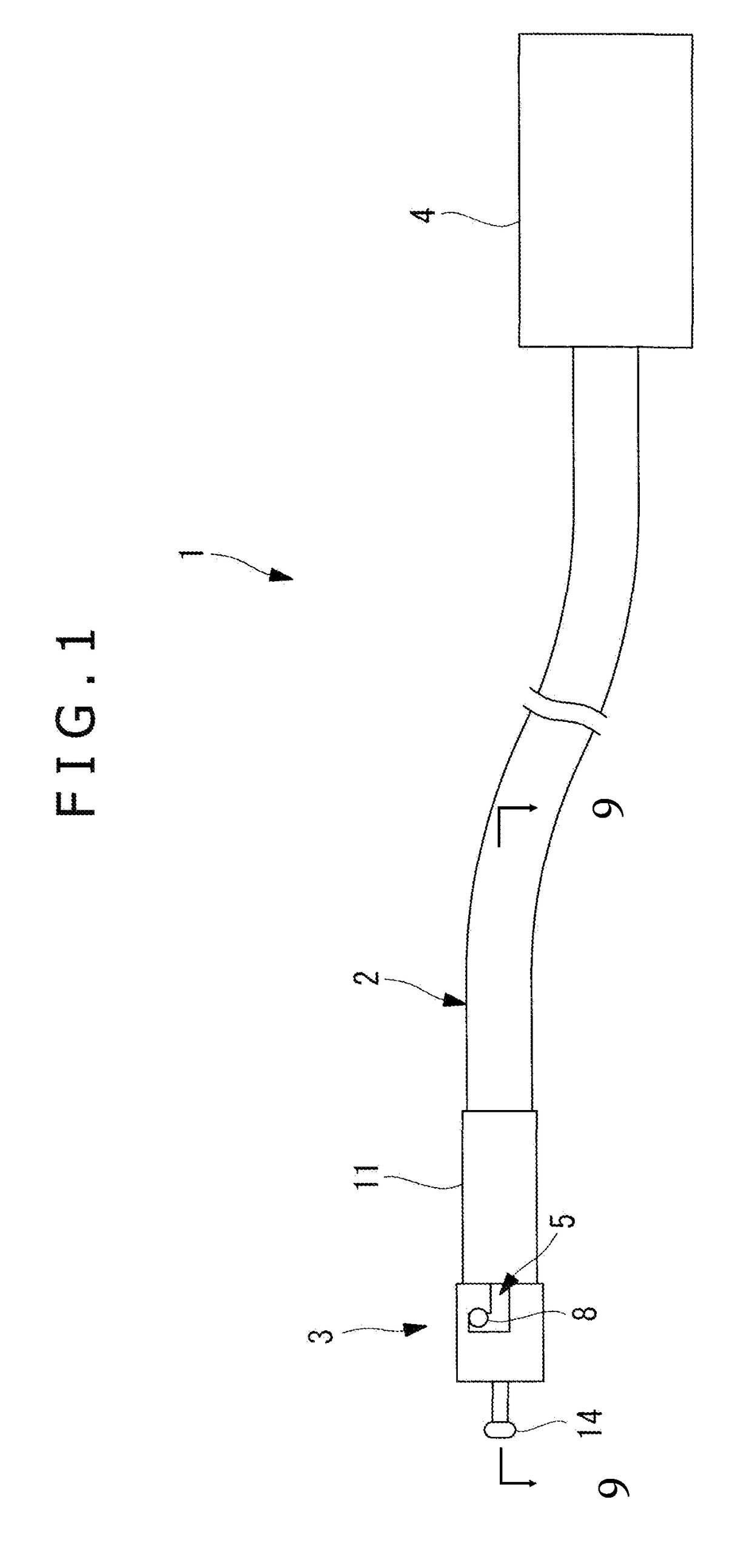
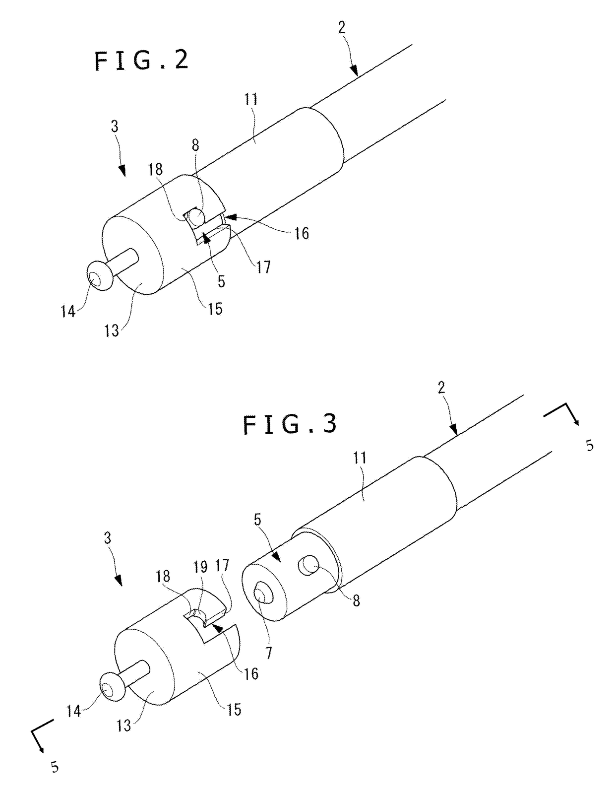
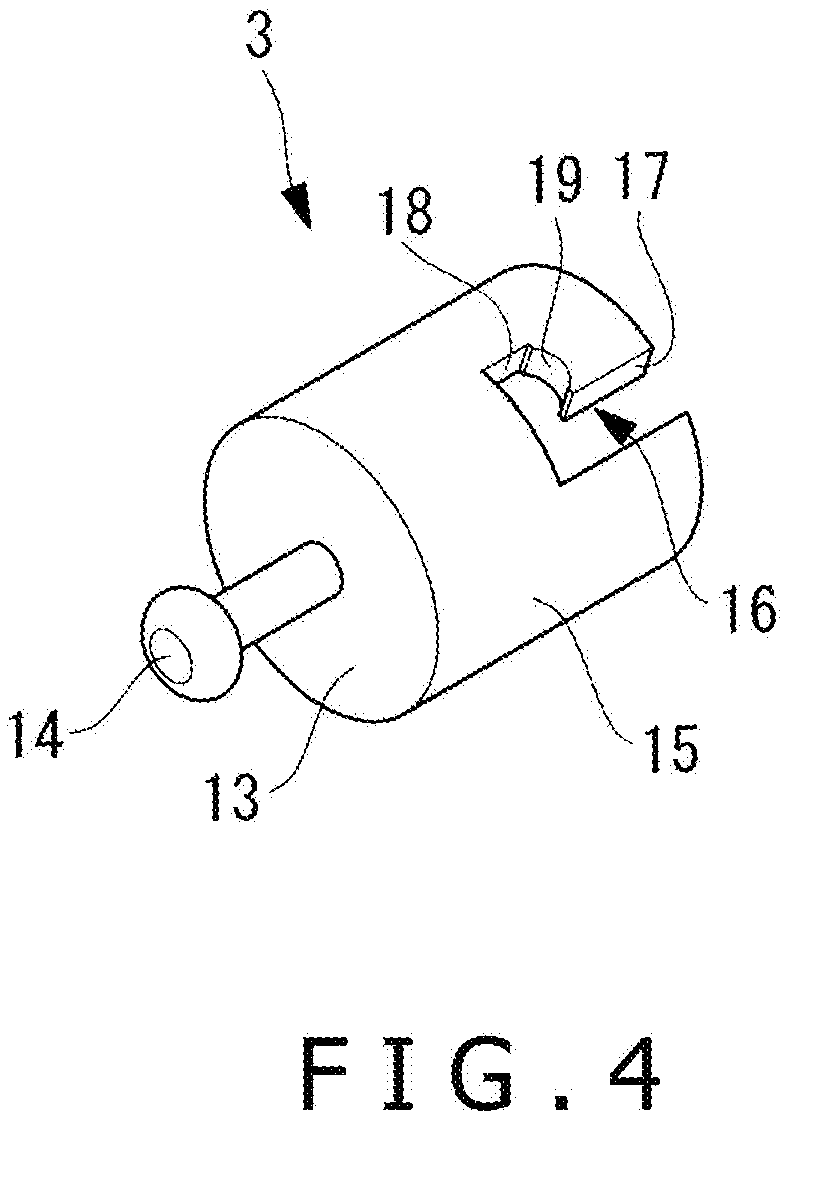
[0008]According to a first aspect of the technology disclosed herein, a medical manipulator comprises an elongated member having a base member on a distal end thereof. An end effector unit is detachably attached to the base member. A proximal end member is connected to a proximal end of the elongated member for actuating the end effector unit. The base member has a surface formed a flat face and / or an outwardly projecting curved face, and a protrusion projecting from the surface in a direction perpendicular to a longitudinal axis of the elongated member. The end effector unit has an engaging portion which engages the protrusion to keep the end effector unit undislodgeably attached to the base member when...
PUM
 Abstract
Description
Claims
Application Information