

Seat with automatic tilting
- Summary
- Abstract
- Description
- Claims
- Application Information
AI Technical Summary
Benefits of technology
Problems solved by technology
Method used
Image

Examples
first embodiment
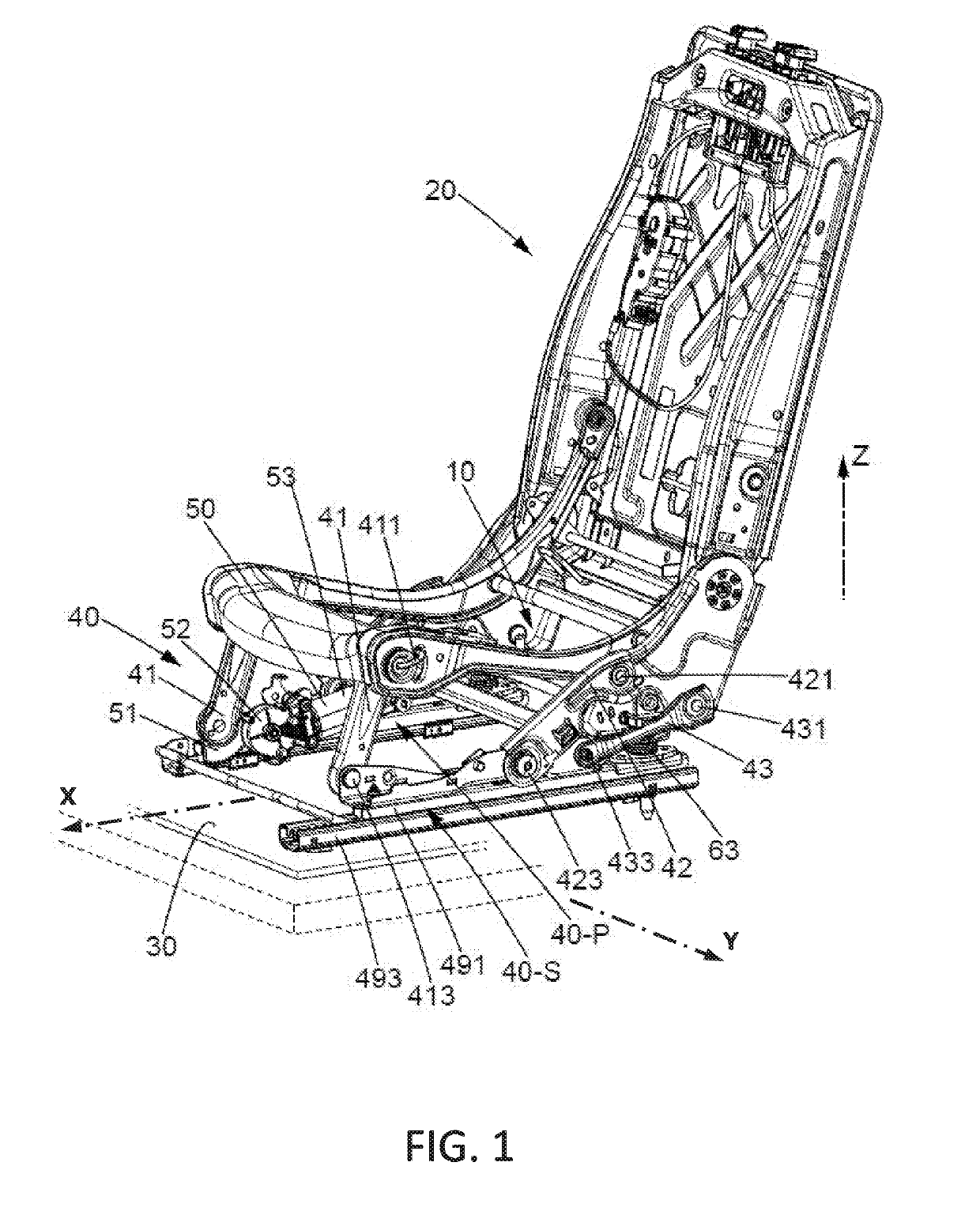
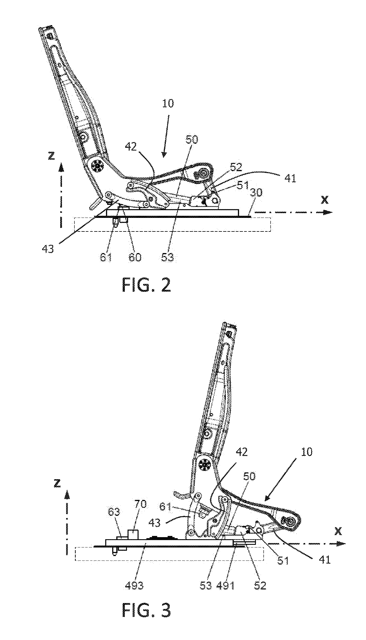
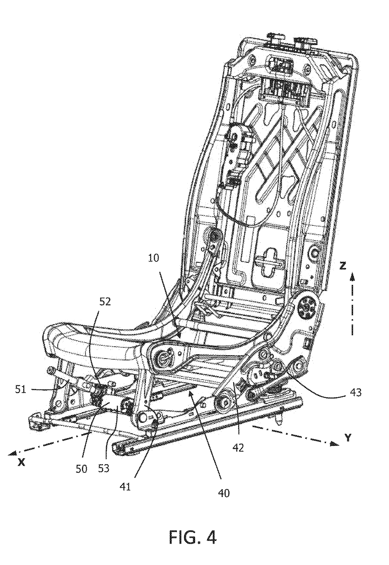
[0057]In the invention, illustrated in FIGS. 1 to 4, the rear hinge of the seating portion 10 comprises four bars (42, 43) and the first motor 50 rotates one of the front connecting rods 41. The first motor 50 comprises a driving member 53 fixed to the slider 491, an actuator 52 which is set in motion directly by the driving member 53, and a displaceable member 51 which is integral with this front connecting rod 41 (if there is no secondary mechanism 40-S, each driving member 53 is fixed to the support 30). The displaceable member 51 engages with the actuator 52 such that the movement of the actuator 52 displaces the displaceable member 51.
[0058]In a first variant illustrated in FIGS. 1 to 3, the actuator 52 is a pinion, and the displaceable member 51 is a toothed circular sector whose teeth mesh with the teeth of the pinion 52 (see FIG. 1, where the seat is in the rest position). Thus, the driving member 53 rotates the pinion 52, which causes the toothed sector 51 to rotate, which ...
second embodiment
[0063]In the invention, illustrated in FIG. 5, the rear hinge of the seating portion 10 comprises two gusset plates 44, and the first motor 50 rotates one of the gusset plates 44.
[0064]The first motor 50 comprises a driving member 53 fixed to the slider 491, an actuator 52 which is set in motion directly by the driving member 53, and a displaceable member 51 which is integral with the gusset plate 44 (if there is no secondary mechanism 40-S, each driving member 53 is fixed to the support 30). The displaceable member 51 engages with the actuator 52 such that the movement of the actuator 52 displaces the displaceable member 51.
[0065]Similarly to the first variant of the first embodiment described above, the actuator 52 is a pinion, and the displaceable member 51 is a toothed circular sector having teeth that mesh with the teeth of the pinion 52. When the driving member 53 rotates the pinion 52, the toothed sector 51 is rotated, which pivots one of the gusset plates 44 forward, about i...
third embodiment
[0066]In the invention, illustrated in FIG. 6, the rear hinge of the seating portion 10 comprises two gusset plates 44, and the first motor 50 rotates one of the front connecting rods 41.
[0067]Similarly to the second variant of the first embodiment described above, the actuator 52 is a pinion and a worm screw, and the displaceable member 51 is a toothed tube of which the teeth mesh with the worm screw (in FIG. 4 the seat is in the rest position). The toothed tube 51 has one end fixed to one of the front connecting rods 41, at a distance from the first front pivot connection 413. Thus, the driving member 53 rotates the worm screw, which moves the toothed tube in translation, which pivots this front connecting rod 41 forward about the first front pivot connection 413. This pivoting of the front connecting rods 41 causes forward rotation of the gusset plates 44 about their first gusset pivot connection 443, which raises the rear of the seating portion 10 and moves the seating portion 1...
PUM
 Abstract
Description
Claims
Application Information