Hammerhead with lateral nail-pulling groove

a lateral nail and groove technology, applied in the field of hammers, can solve the problems of difficult to maneuver the hammer, the claw may not be easily attached to the nails to be pulled, and the difficulty of pulling the nails with a conventional claw hammer, so as to avoid accidental injury

Inactive Publication Date: 2010-02-18
CHEN YUNG SHOU
View PDF6 Cites 19 Cited by
  • Summary
  • Abstract
  • Description
  • Claims
  • Application Information

AI Technical Summary

Benefits of technology

[0007]According to another aspect of the present invention, the hammerhead further comprises a side gap at one or each of the two opposite lateral sides thereof between the claw and the two cheeks. When pulling a nail with one V-groove, the head of the nail to be pulled is received in the associating side gap. When the user turned the hammer sideways to pull the nail out of the wood, the nail is kept in the V-groove and will not jump away, avoiding accidental injury.

Problems solved by technology

However, a hammer may be used in environments in which it is difficult to maneuver the hammer.
For pulling nails in a narrow space or corner area, the claw may be not smoothly attachable to the nails to be pulled.
In that case, it is difficult to pull the nails with a conventional claw hammer.

Method used


Image

  • Hammerhead with lateral nail-pulling groove
  • Hammerhead with lateral nail-pulling groove
  • Hammerhead with lateral nail-pulling groove

Examples


Embodiment Construction

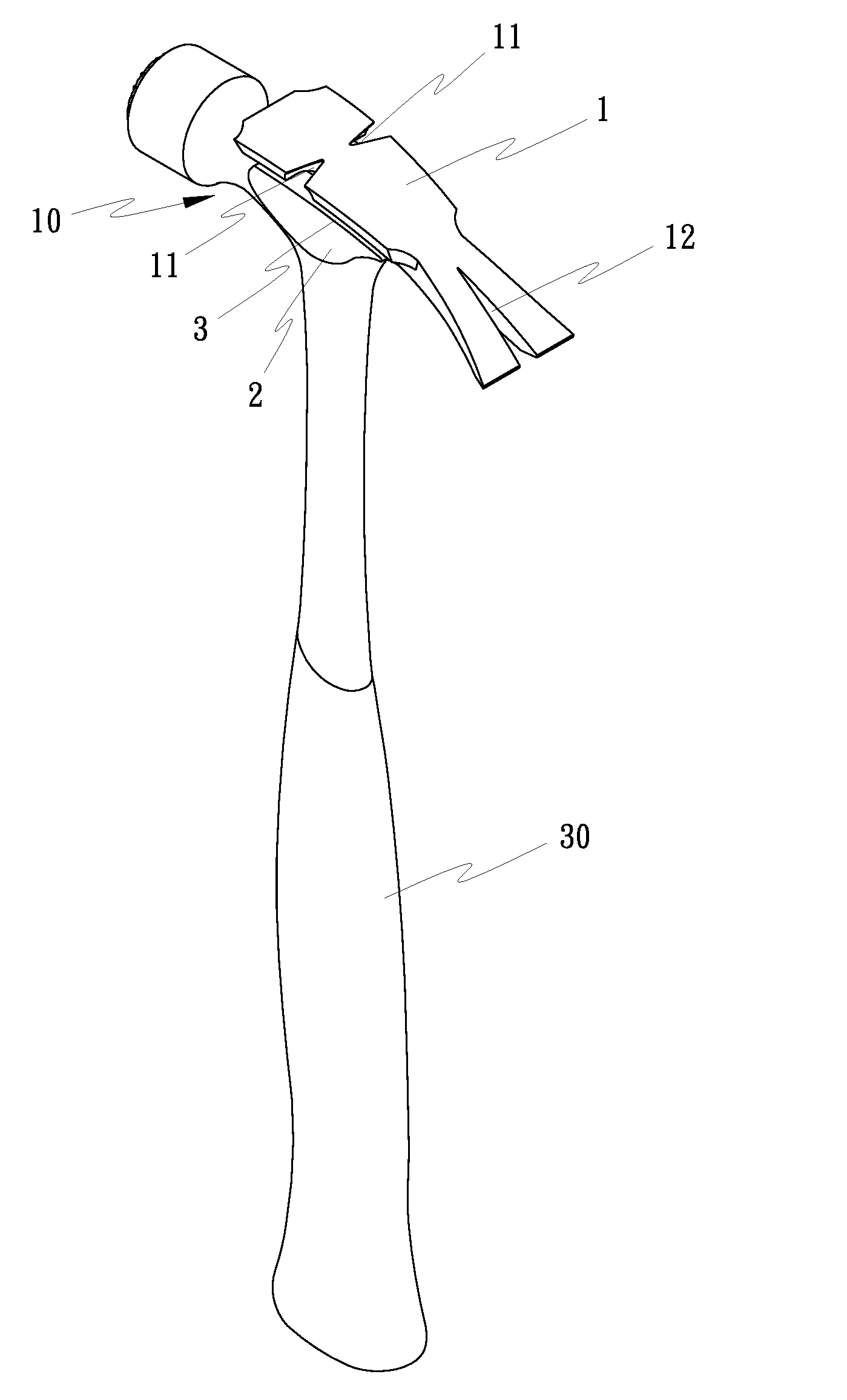
[0013]As shown in FIG. 1, a hammer with lateral nail-pulling function in accordance with the present invention comprises a handle 30 and a hammerhead 10 at one end of the handle 30. The hammerhead 10 comprises a claw 1, two cheeks 2 at two opposite lateral sides, and a side gap 3 at each of the two opposite lateral sides between the claw 1 and the cheeks 2. The claw 1 has a V-groove 11 transversely disposed at each of the two opposite lateral sides thereof for pulling nails sideways.

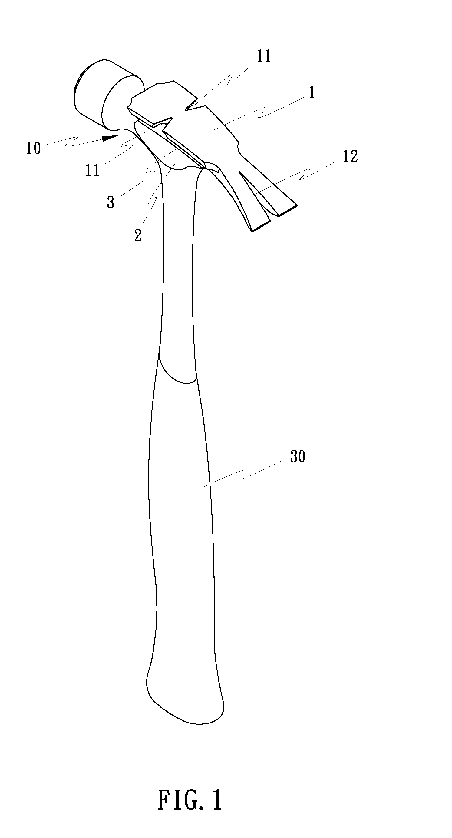
[0014]Referring to FIGS. 2 and 3 and FIG. 1 again, by means of the side gap 3 at each of the two opposite lateral sides between the claw 1 and the cheeks 2, one V-groove 11 of the claw 1 can be attached to a nail 20 in the wood to receive the head 201 of the nail 20 in the corresponding side gap 3 so that the hammer can be turned sideways to pull the nail 20 out of the wood.

[0015]Referring to FIGS. 4 and 5, one V-groove 11 of the claw 1 can be attached to a nail 20 in a narrow space or near a side corner...


PUM


Abstract

A hammerhead having a claw, two cheeks and a V-groove at each of two opposite lateral sides of the claw for pulling nails sideways and a side gap between each of the two cheeks and the claw for receiving the head of the nail to be pulled sideways with the V-groove.

Description

BACKGROUND OF THE INVENTION[0001](a) Field of the Invention[0002]The present invention relates to hammers and, more particularly, to a hammerhead that has a V-groove at each of two opposite lateral sides of the claw of the hammerhead for pulling nails sideways.[0003](b) Description of the Prior Art[0004]A claw hammer generally comprises a handle and a metal hammerhead having a claw at the front side and a bell at the rear side. The claw has a V-groove for pulling nails in the forward direction. However, a hammer may be used in environments in which it is difficult to maneuver the hammer. For pulling nails in a narrow space or corner area, the claw may be not smoothly attachable to the nails to be pulled. In that case, it is difficult to pull the nails with a conventional claw hammer.SUMMARY OF THE INVENTION[0005]The present invention has been accomplished under the circumstances in view. It is one object of the present invention to provide a hammer with a specifically designed hamme...

Claims


Application Information

Patent Timeline
Patent Type & Authority Applications(United States)
IPC IPC(8): B25D1/04
CPCB25D1/04
Inventor CHEN, YUNG-SHOU
Owner CHEN YUNG SHOU
Why Eureka
Try Eureka