
Device for intracavity in-situ fenestration and puncture

A fenestration, in-situ technology, applied in the field of medical devices, can solve the problems of inability to precisely adjust the puncture depth, accidental injury to the contralateral tissue, and excessive puncture depth, etc., to reduce risks, concentrate puncture, and improve effectiveness.

Active Publication Date: 2017-07-21
HANGZHOU WEIQIANG MEDICAL TECH CO LTD
View PDF10 Cites 25 Cited by
  • Summary
  • Abstract
  • Description
  • Claims
  • Application Information

AI Technical Summary

Problems solved by technology

[0007] The technical problem to be solved by the present invention is that the puncture depth cannot be precisely adjusted, and it is easy to cause the puncture depth to be too long to accidentally injure the contralateral tissue, and the puncture depth is not enough to cause the puncture to fail. Adjustable, can lock the puncture depth, and accurately puncture to keep the puncture point in the center of the branch blood vessel in-situ fenestration puncture device

Method used


Image

  • Device for intracavity in-situ fenestration and puncture
  • Device for intracavity in-situ fenestration and puncture
  • Device for intracavity in-situ fenestration and puncture

Examples


Embodiment 1

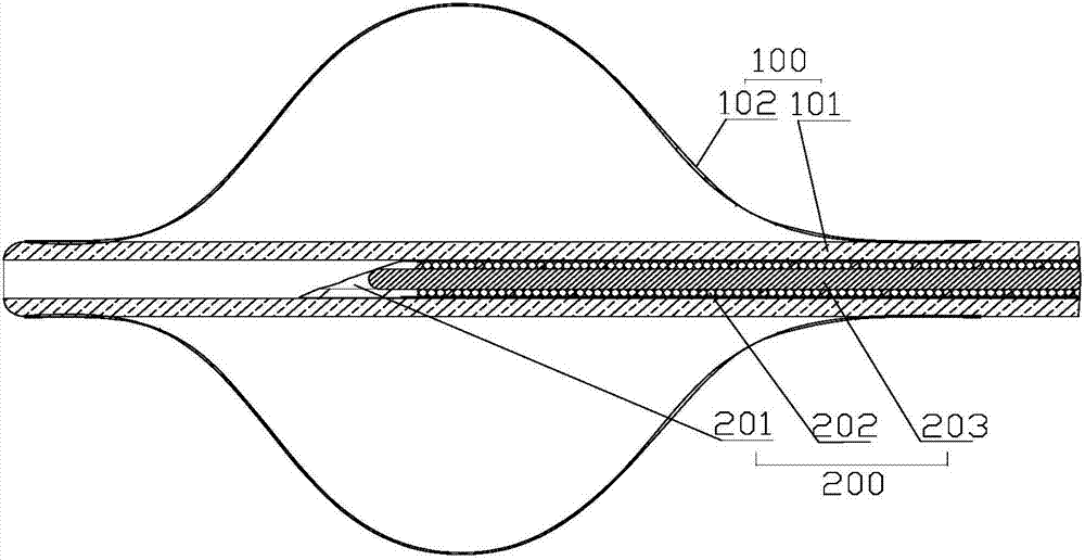
[0046] Embodiment 1, the main technical problem to be solved in this embodiment is to precisely control the puncture depth, adjust the puncture depth and lock the puncture, and solve the problem of accurate puncture, that is, ensure that the puncture position is in the center of the blood vessel. Such as Figure 1-17 As shown, a puncture device for intraluminal in situ fenestration includes a balloon catheter 100 and a puncture needle assembly 200 coaxially sleeved in the balloon catheter 100; the balloon catheter 100 includes at least two cavities The balloon pusher rod 101, the balloon body 102 arranged at the distal end of the balloon pusher rod 101, the balloon catheter seat 103 arranged at the proximal end of the balloon pusher rod 101; the puncture needle assembly 200 includes a puncture pusher rod 202, The puncture needle 201 and the puncture handle 205 arranged at the distal end of the puncture push rod 202; the puncture handle 205 includes a proximal handle 252 and a ...

Embodiment approach

[0057] Such as Figure 12 Shown is the first embodiment of the puncture control mechanism 206, which can be driven quickly to achieve puncture, and realize quantitative and precise puncture. The maximum stroke control assembly 260 includes a stroke groove 260a arranged on the proximal handle 252 or the distal handle 251, and the corresponding distal handle 251 or the proximal handle 252 is provided with a limit block 260b; The puncture push rod 202 is arranged axially, and the limit block 260b slides in the travel groove 260a and its maximum sliding distance is the maximum depth that allows the puncture needle to puncture. The maximum depth is determined according to the diameter of the blood vessel, usually not exceeding 40mm. The lateral width of the stroke groove 260a is slightly larger than that of the limiting block 260b, and the two are clearance fit or sliding fit.

[0058]The puncture locking assembly 261 is provided with a plurality of positioning locking grooves 261...

Embodiment 2

[0064] Embodiment 2, the main technical problem to be solved in this embodiment is: the puncturing push rod 202 is not easy to be discounted, and the puncturing is more concentrated and effective.

[0065] A puncture device for intraluminal in situ fenestration, comprising a balloon catheter 100 and a puncture needle assembly 200 coaxially sleeved in the balloon catheter 100; the balloon catheter 100 includes a balloon pusher with at least two cavities rod 101, the balloon body 102 arranged at the distal end of the balloon push rod 101, the balloon catheter seat 103 arranged at the proximal end of the balloon push rod 101; The puncture needle 201 and the puncture handle 205 at the far end of the push rod 202; Lining silk 203. The concrete structure of above-mentioned parts is the same as embodiment 1.

[0066] Wherein the structure of the balloon catheter 100 can be the same as that of Embodiment 1, including the balloon pushing rod 101 and the balloon body 102, but the ball...


PUM


Abstract

The invention discloses a device for intracavity in-situ fenestration and puncture. The device comprises a balloon catheter and a puncture needle assembly, wherein the balloon catheter is internally and coaxially sleeved with the puncture needle assembly. The balloon catheter comprises a balloon push rod with at least two cavities, a balloon body and a balloon catheter base, wherein the balloon body is mounted at the distal end of the balloon push rod, and the balloon catheter base is mounted at the proximal end of the balloon push rod. The puncture needle assembly comprises a puncture push rod, a puncture needle and a puncture handle, wherein the puncture needle is mounted at the distal end of the puncture push rod. The puncture handle comprises a proximal handle and a distal handle, wherein the distal handle is fixedly or removably fixedly connected to the balloon catheter base; the proximal handle is connected to the puncture push rod and disposed in the direction of the distal handle. A puncture control structure is disposed between the distal and proximal handles, and used for controlling puncture depth of the puncture needle and locking the puncture needle. The device for intracavity in-situ fenestration and puncture is capable of precisely controlling the puncture depth, adjusting the puncture depth, locking the puncture needle, and precisely puncturing and maintaining puncture sites at the center of branch blood vessels.

Description

technical field [0001] The invention belongs to the technical field of medical devices, and relates to an intracavity interventional device, in particular to a puncture device for in-situ fenestration in a cavity. Background technique [0002] With the continuous development of endovascular reconstruction surgery, the application of covered stents is also increasing, but the use of covered stents in some special parts will affect the blood supply of arterial branch vessels, such as the aortic arch, celiac trunk, and bilateral renal arteries. And the superior mesenteric artery and other parts, so that the use of covered stent grafts in these parts is greatly limited. At present, the stent surgery of the above-mentioned parts can only be performed through the improvement of surgical methods, such as the use of hybrid surgery, or the improvement of equipment, such as modular stents, pre-fenestrated stents, branch stents, multi-layer bare stents, etc., but For the vast majority...

Claims


Application Information

Patent Timeline
Patent Type & Authority Applications(China)
IPC IPC(8): A61F2/07A61F2/954A61F2/958
CPCA61F2/07A61F2/954A61F2/958
Inventor 李阳张庭超
Owner HANGZHOU WEIQIANG MEDICAL TECH CO LTD
Learn More