Clip on cover for sink traps

a sink and cover technology, applied in the field of trap fittings, to achieve the effect of preventing burns, reducing the weight of the trap, and preventing dust collection on the trap

Inactive Publication Date: 2019-03-28
OAKVILLE STAMPING & BENDING
View PDF3 Cites 0 Cited by
  • Summary
  • Abstract
  • Description
  • Claims
  • Application Information

AI Technical Summary

Benefits of technology

[0015]The Invention, a clip on cover for sink traps, presents a cover for the trap which is clipped onto the vertical portion of the upstream part of the trap by means of a plurality of clips that fit onto the trap. An uppermost clip fits to the diameter of the threaded drain plug. Optional support by a nut adds an advantage over any other slip joint trap by allowing the Invention to also act as a trap support and relieve the weight of the trap from the wall bend. This requires another clip to clip onto the upstream arm of the trap itself. In order that water not collect, a substantial drainage cavity is provided in the base of the cover sized to avoid blockage.
[0016]By use of appropriate spacers between the plurality of clips and the cover, the Invention achieves trap cover the first design objective by providing airspace between the trap and the cover, preventing burns. The invention satisfies the second cover design objective two through providing an easily wiped trap cover, to prevent dust collection on the trap. The clips allow easy removal and replacement, to enable removal of a trap cleanout such as a detachable U-bend, to enable maintenance as in the third trap cover design objective. Through provision of a substantial drainage cavity freely allows water dripping from a perforated trap to drip to the floor to provide evidence of trap failure, allowing attainment of the fourth design objective. Trap cover design objective five is achieved since there is no potential for a secondary pool for water to collect. Trap cover design objective six is achieved by provision to fit a variety of trap designs and technologies. The clip on design also allows for a diversity of covers to be used independent of the form factor of the underlying trap.

Problems solved by technology

Accordingly, it is an objection of this Invention to at least partially overcome some of the disadvantages of the prior art.

Method used


Image

  • Clip on cover for sink traps
  • Clip on cover for sink traps
  • Clip on cover for sink traps

Examples


Embodiment Construction

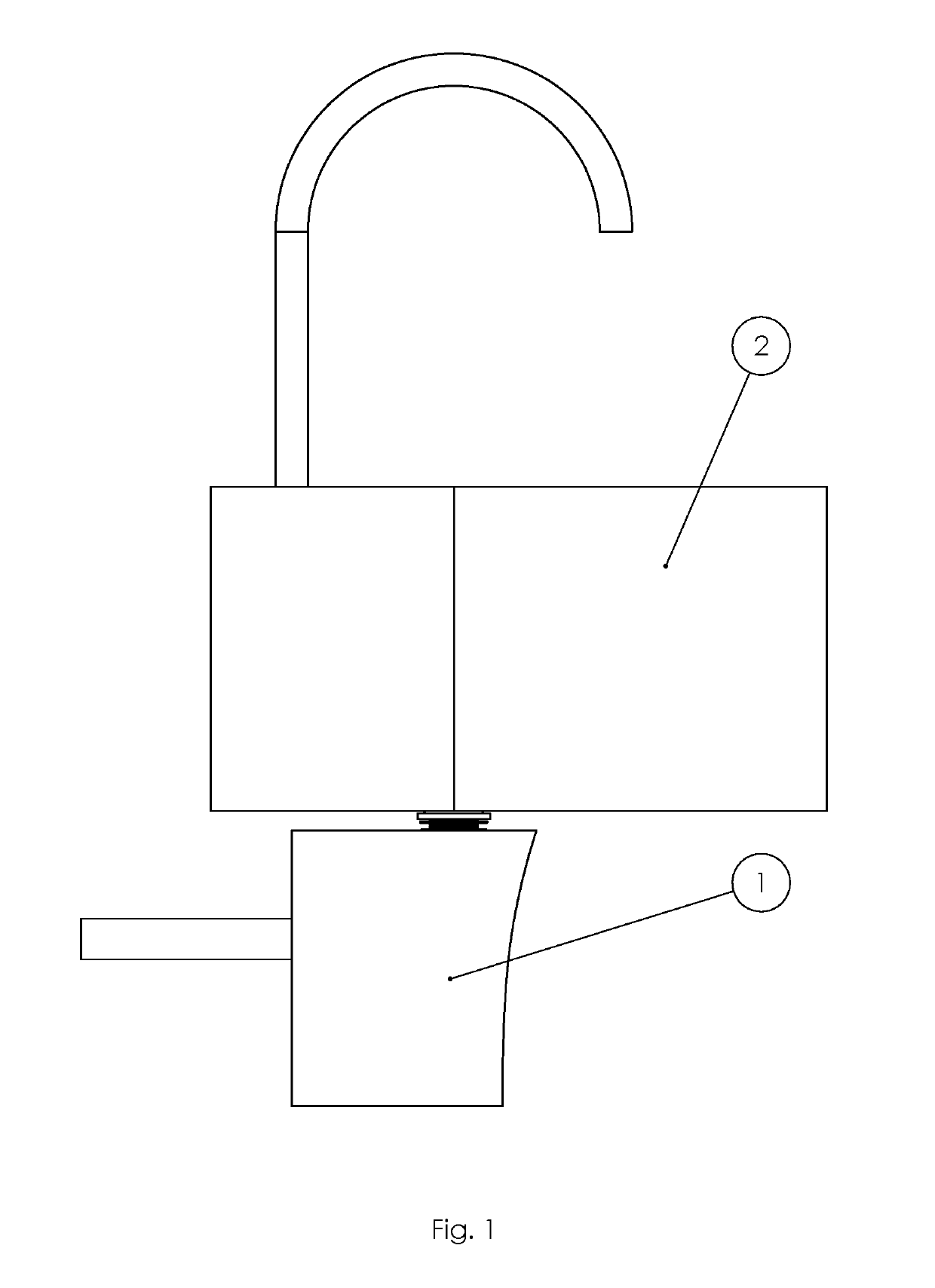
[0021]The Invention described in this Application is a novel clip on cover fitting for a plurality of traps for lavatory sinks. An isometric view of the entire removable cover system is shown in FIG. 1 as attached to a typical lavatory sink trap that might be secured to a wall or counter by a plurality of means. The cover 1 is visible beneath the sink 2.

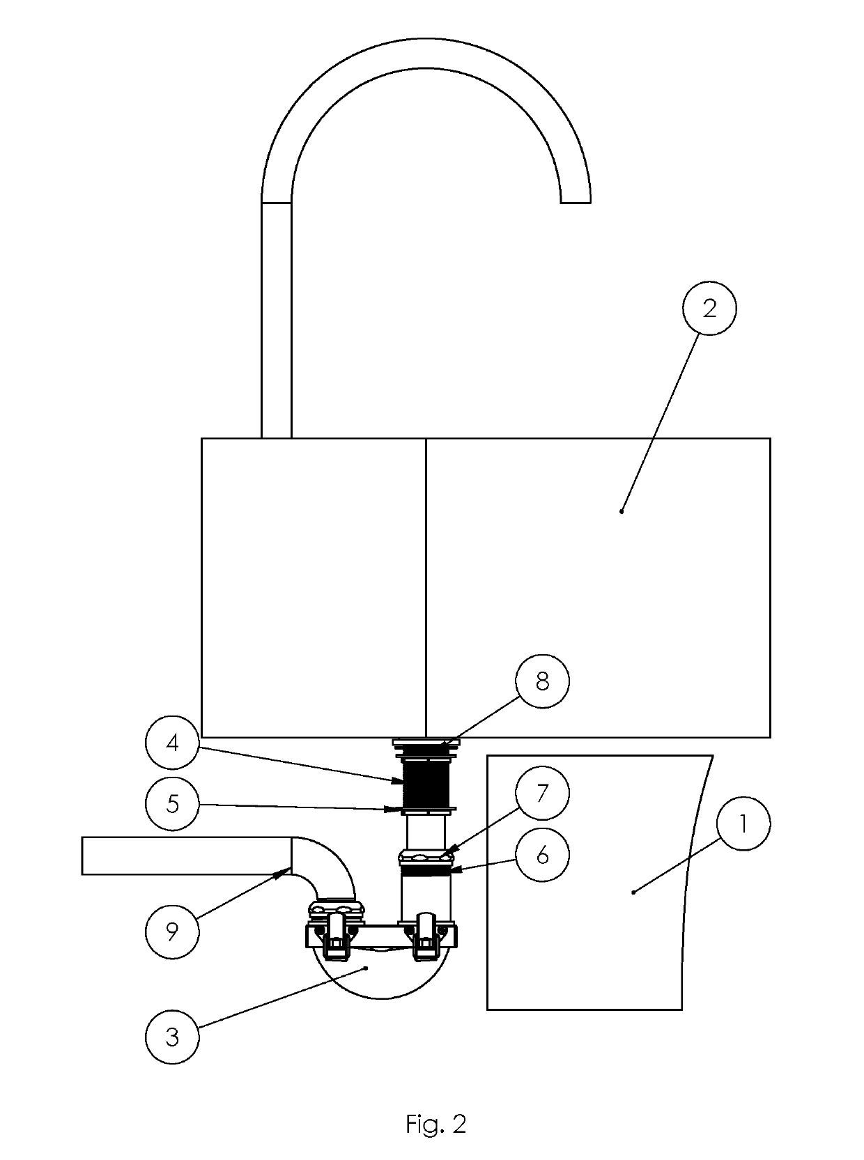
[0022]An exploded view of the Invention described in this Application shows the cover 1 as removed from the trap 3 attached in turn to the sink 2. Attachment points for clips include the threaded diameter of the drain plug 4 with an optional support by a nut 5. If another clip is attached to the internal side of the cover, this second clip can attach to the upstream portion 6 of the trap 3 beneath the slip joint nut 7, providing a novel limiter on slip joint movement. Sinks are well mounted, particularly in hospital; therefore, by hanging the weight of the trap 3 on the drain plug 4 hanging from and cinched to the sink 2 by means of ...


PUM


Abstract

A clip on cover for sink traps is provided to allow prevention of burns to the legs of wheelchair users of the sink through isolating the trap at a distance from the cover and thus at a distance from the legs of the wheel chair user. The cover enables a range of form factors to be covered without the collection of leak water, allows leaks in the trap to be detected, and provides aesthetic flexibility and access for trap hygiene maintenance. The clip on cover enables easy cleaning and access for trap maintenance. By linking the weight of the trap indirectly to the sink mount through placement of clips such that the upper clip engages the fixed drain plug and the lower drain plug engages the trap upstream arm, strain on the downstream, horizontal, wall bend is relieved.

Description

CROSS-REFERENCE TO RELATED APPLICATIONS[0001]No cross reference is made to other applications.STATEMENT REGARDING FEDERALLY SPONSORED RESEARCH OF DEVELOPMENT[0002]No Federal Government support was received in the development of this Invention.SEQUENCE LISTING, TABLE, OR COMPUTER PROGRAM LISTING[0003]No sequence listing, table, or computer program is attached or accompanies this Application.FIELD OF THE INVENTION[0004]This Invention relates generally to trap fittings connected to lavatory sinks, and more particularly to covers for traps fitted to lavatory sinks.BACKGROUND OF THE INVENTION[0005]The advent of accessibility requirements in public and private buildings have led to a category of products comprising covers that fit to the trap of a sink. The design intention of trap covers is to prevent the legs and knees of a wheelchair user using a sink from suffering skin burns owing to not being able to sense the hot temperature of drainage water passing from the sink vessel, around th...

Claims


Application Information

Patent Timeline
Patent Type & Authority Applications(United States)
IPC IPC(8): E03C1/284
CPCE03C1/284E03C2001/321
Inventor MCLEOD, CHRISTOPHER ADAM
Owner OAKVILLE STAMPING & BENDING
Why Eureka
Try Eureka