Torsion device and torsion washer

Active Publication Date: 2019-03-28
FIRST DOME
View PDF3 Cites 1 Cited by
  • Summary
  • Abstract
  • Description
  • Claims
  • Application Information

AI Technical Summary

Benefits of technology

The patent text describes a mechanism that allows for easy adjustment of torque between two parts, such as a shaft and a torsion-adjusting arm. The mechanism is designed to produce a stable torque even at different values. To reduce friction between the parts, each torsion washer is equipped with a slot to hold lubricating oil. The result is a mechanism that helps to improve the performance of the system and reduce wear and tear.

Problems solved by technology

A conventional torsion washer does not have a structure which allows for receiving a lubricating oil, and provides only a torsion of fixed value, so that the conventional torsion washer cannot be applied to a device having different torque demands.

Method used


Image

  • Torsion device and torsion washer
  • Torsion device and torsion washer
  • Torsion device and torsion washer

Examples


first embodiment

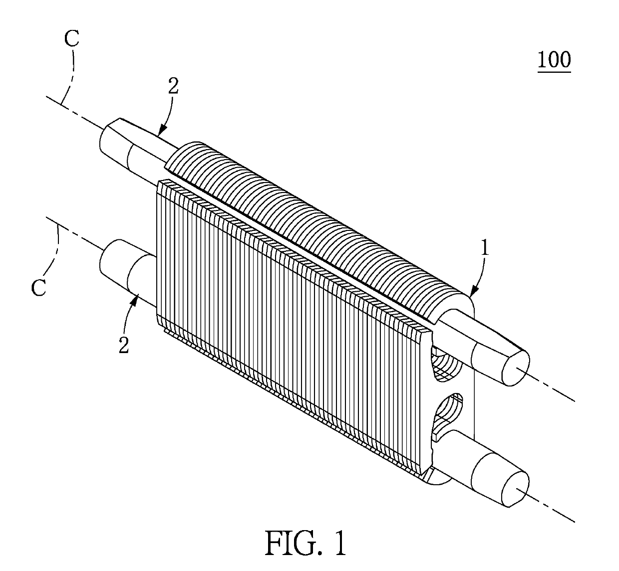
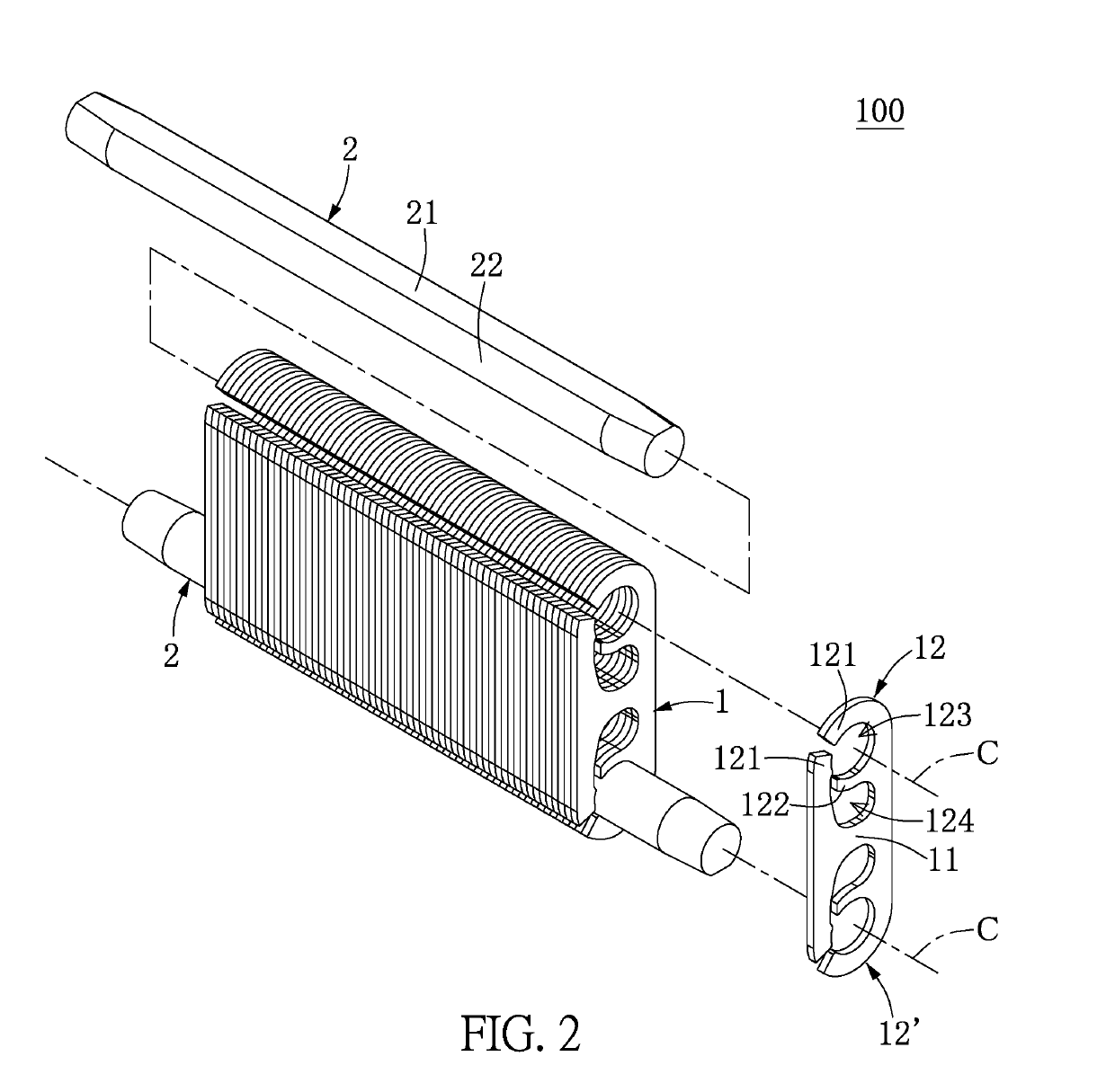
[0023]Reference is made to FIGS. 1 to 7, which illustrate a first embodiment of the present disclosure. As shown in FIGS. 1 and 2, the present embodiment discloses a torsion device 100 for being applied to different torque demands. For example, a touch-control screen of a notebook PC can be raised from a closed position by using a lower torque, but when the touch-control screen and the keyboard of the notebook PC have an angle within a range of 85˜110 degrees, the touch-control screen needs to receive a higher torque for its touch-control function. The torsion device 100 includes a plurality of torsion washers 1 stacked in one row and two shafts 2 coupling through the stacked torsion washers 1, and the outer edges of the torsion washers 1 are flush with each other.

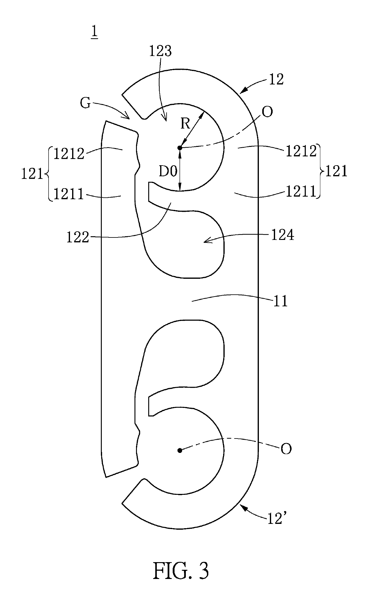
[0024]Specifically, each of the torsion washers 1 has a base portion 11 and two elastic units 12, 12′ respectively extended from two opposite ends of the base portion 11. Each of the torsion washers 1 in the present embodi...

second embodiment

[0039]Reference is made to FIGS. 8 and 9, which illustrate a second embodiment of the present disclosure. The second embodiment is similar to the first embodiment, and the difference between the second embodiment and the first embodiment is that the torsion washers 1 of the present embodiment do not have the same structure.

[0040]Specifically, the torsion washers 1 of the present embodiment include a plurality of first torsion washers 1a and a plurality of second torsion washers 1b. Each of the first torsion washers 1a can be substantially identical to the torsion washer 1 as shown in FIGS. 3 and 4, and each of the second torsion washers 1b can be formed as shown in FIG. 9. Moreover, a central angle (σ1) of the torsion-adjusting arm 122 of each of the first torsion washers 1a is different from a central angle (σ1′) of the torsion-adjusting arm 122 of each of the second torsion washers 1b. Thus, the torsion device 100 of the present embodiment can provide torque having more than three...

third embodiment

[0041]Reference is made to FIGS. 10 to 13, which illustrate a third embodiment of the present disclosure. The third embodiment is similar to the first embodiment, and the difference between the third embodiment and the first embodiment is the structure of the shaft 2.

[0042]Specifically, the shaft 2 includes a first segment 2a and a second segment 2b, and the first segment 2a and the second segment 2b can be integrally formed as one piece (as shown in FIG. 10) or be two separate pieces (as shown in FIG. 12). The first segment 2a couples through a part of the torsion washers 1, and the second segment 2b couples through the other part of the torsion washers 1. Moreover, the first segment 2a can be substantially identical to the shaft 2 as shown in FIG. 4, and the second segment 2b can be formed as shown in FIG. 11 or 13. In the present embodiment, a central angle (σ3) of the non-contact surface 21 of the first segment 2a is different from a central angle (σ3′) of the non-contact surfac...


PUM


Abstract

A torsion washer of the present disclosure includes a base portion and an elastic unit extended from the base portion. The elastic unit includes an external elastic arm and a torsion-adjusting arm arranged inside the external elastic arm. A space surrounded by the base portion and the external elastic arm is divided into a hole and a slot, in air communication with the hole, by using the torsion-adjusting arm. A distance, i.e., a radius, between the external elastic arm and a center of the hole is larger than a distance, i.e., an interference distance, between the torsion-adjusting arm and the center of the hole. Moreover, the present disclosure provides a torsion device including a plurality of the torsion washers and a shaft coupling through the holes of the torsion washers, and the shaft is configured to selectively contact each torsion-adjusting arm.

Description

BACKGROUND OF THE INVENTION1. Field of the Invention[0001]The present disclosure relates to a torsion structure; in particular, to a torsion device and a torsion washer.2. Description of Related Art[0002]A conventional torsion washer does not have a structure which allows for receiving a lubricating oil, and provides only a torsion of fixed value, so that the conventional torsion washer cannot be applied to a device having different torque demands.SUMMARY OF THE INVENTION[0003]The present disclosure provides a torsion device and a torsion washer to solve the problem associated with conventional torsion washers.[0004]The present disclosure provides a torsion device including a plurality of torsion washers and at least one shaft. The torsion washers are stacked in one row and each has a base portion and at least one elastic unit extended from the base portion. The at least one elastic unit of each of the torsion washers includes at least one external elastic arm and a torsion-adjustin...

Claims


Application Information

Patent Timeline
IPC IPC(8): F16B43/00
CPCF16B43/00E05D2011/085E05D11/084E05Y2201/476E05Y2201/484F16B43/025F16F1/027F16F3/02
Inventor CHIANG, I-HUNG
Owner FIRST DOME
Why Eureka
Try Eureka