Photoelectric Switch And Sensor Unit

Active Publication Date: 2019-03-28
KEYENCE
View PDF0 Cites 0 Cited by
  • Summary
  • Abstract
  • Description
  • Claims
  • Application Information

AI Technical Summary

Benefits of technology

[0008]According to the present invention, the cover member holds a display provided on the outer surface of t

Problems solved by technology

However, in recent years, according to the upgrading of photoelectric switches, the seven-segment display has been unable

Method used


Image

  • Photoelectric Switch And Sensor Unit
  • Photoelectric Switch And Sensor Unit
  • Photoelectric Switch And Sensor Unit

Examples


Example

[0022]An embodiment of the present invention is explained below. The individual embodiment explained below would be useful for understanding various concepts such as a superordinate concept, an intermediate concept, and a subordinate concept of the present invention. The technical scope of the present invention is decided by the claims and is not limited by the individual embodiment explained below.

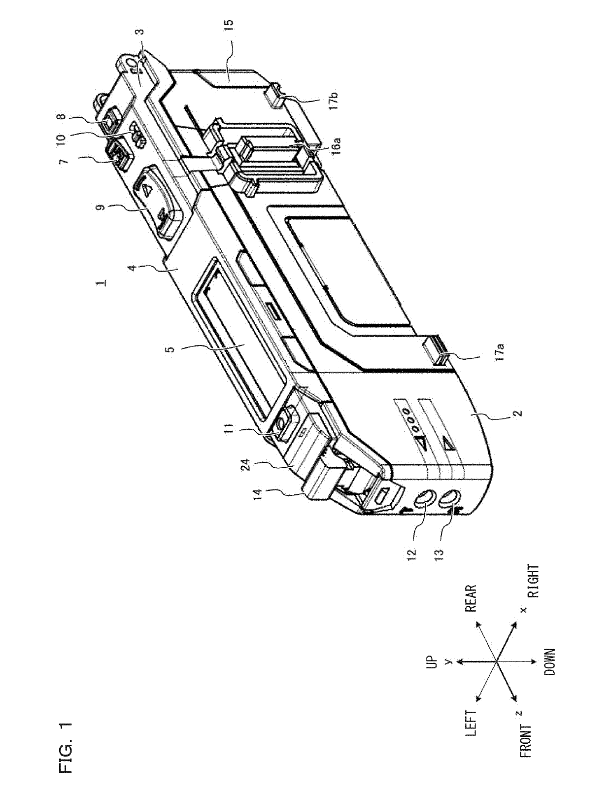
[0023]FIG. 1 is a perspective view showing a photoelectric switch. A photoelectric switch 1 includes a substantially rectangular housing. In FIG. 1, a z axis corresponds to a longitudinal direction, an x axis corresponds to a latitudinal direction, and a y axis corresponds to a height direction. The housing generally has six outer surfaces. The six outer surfaces include an upper surface, a bottom surface, a front surface, a rear surface, a left side surface, and a right side surface. In FIG. 1, the upper surface, the front surface, and the right side surface are seen. The housing include...


PUM


Abstract

To make a display in a photoelectric switch easy to see for a user. A photoelectric switch includes a housing having a substantially rectangular parallelepiped shape. A display is attached to a first surface of the outer surface of the housing. A control board is housed on the inside of the housing. A controller is mounted on the control board. The first surface includes a hole-like or cutout-like opening section for allowing a signal cable to pass from the outside to the inside of the housing. The signal cable electrically connects the control board disposed on the inside of the housing and the display disposed on the outside of the housing. A cover member includes a window section for exposing a display region of the display and covers a non-display region of the display. The cover member is provided outside the housing.

Description

CROSS-REFERENCE TO RELATED APPLICATIONS[0001]The present application claims foreign priority based on Japanese Patent Application No. 2017-186813, filed Sep. 27, 2017, the contents of which is incorporated herein by reference.BACKGROUND OF THE INVENTION1. Field of the Invention[0002]The present invention relates to a photoelectric switch and a sensor unit.2. Description of Related Art[0003]A product (work) produced in a factory is conveyed by a conveying apparatus such as a belt conveyor. Arrival of the work at a predetermined place is detected by a photoelectric switch. In general, the photoelectric switch projects light toward the work or the like, receives reflected light from the work, and displays a numerical value indicating a light receiving amount and a threshold compared with the numerical value on a seven-segment display (JP-A-2003-141961). When detecting the work on the basis of the light receiving amount and the threshold, the photoelectric switch outputs an ON signal th...

Claims


Application Information

Patent Timeline
IPC IPC(8): G01J1/02G01J1/04G01V8/16H02B1/052H01L27/32H03K17/94
CPCG01J1/0271G01J1/0425G01V8/16H02B1/052H01L27/3244H03K17/941H03K17/78H03K17/96H03K2217/96015H03K17/943H03K2217/9401H03K2217/94026H03K2217/94108H10K59/12
Inventor OH, CHORYONKOJIMA, KENJI
Owner KEYENCE
Why Eureka
Try Eureka