Leak sensor assemblies and systems utilizing same

a sensor and leakage technology, applied in the field of leakage sensor assemblies and systems utilizing same, can solve the problems of not meeting the national ambient air quality standard (“naaqs”), aggravate respiratory diseases, and many complex issues

Inactive Publication Date: 2019-03-28
MOLEX INC
View PDF0 Cites 27 Cited by
  • Summary
  • Abstract
  • Description
  • Claims
  • Application Information

AI Technical Summary

Problems solved by technology

Process plants, such as petroleum refineries and chemical manufacturing facilities, have many complex issues associated with gas leaks.
Ozone is a major component of smog, and may cause or aggravate respiratory disease.
Many areas of the United States, particularly those areas where refineries and chemical facilities are located, do not meet the National Ambient Air Quality Standard (“NAAQS”) for ozone.
Leaks from valves usually occur at the stem or gland area of the valve body and are commonly caused by failure of the valve packing or O-ring.
Leaks from connectors are commonly caused from gasket failures and improperly torqued bolts on flanges.
Leaks from pressure relief valves can occur if the valve is not sealed properly, operating too close to the set point, or if the seal is worn or damaged.
Leaks from rupture disks can occur around the disk gasket if not properly installed.
Leaks can also be caused by the incorrect implementation of the block and bleed procedure.
The major cause of emissions is seal or gasket failure due to normal wear or improper maintenance.
Leakless and seal less components can be effective at minimizing or eliminating leaks, but their use may be limited by materials of construction considerations and process operating conditions.
Installing leakless and seal less components can also be expensive and time-consuming, possibly even requiring a shut-down of all or a part of a facility.
While the manual use of a probe is an effective way of monitoring the components for leaks, the manual use has several disadvantages associated with it.
More specifically, the manual use of a probe is typically performed by a large pool of skilled labor and / or engineers and, thus, tends to have high associated costs to execute, especially as the manual use of a probe to monitor hundreds of thousands of components can be rather time consuming.
These infrared cameras are fast in identifying locations of large leaks, but they do not provide quantitative results and they do not offer the same level of sensitivity as conventional Method 21 instruments.
These systems, however, suffer from outdoor environmental conditions, such as wind, rain, and temperature variations.
In order to detect and quantify the leak, the sensor must be placed exactly at the leak location, but the odds of this occurring are not likely and, furthermore, those odds are not odds that are acceptable to the process plants and / or the EPA.
Since the negatives associated with using sensors have not been overcome, the tried-and-true method of manual monitoring with an expensive handheld device to reliably locate and quantify the leak continue to be used.

Method used


Image

  • Leak sensor assemblies and systems utilizing same
  • Leak sensor assemblies and systems utilizing same
  • Leak sensor assemblies and systems utilizing same

Examples


Embodiment Construction

[0071]While the disclosure may be susceptible to embodiment in different forms, there is shown in the drawings, and herein will be described in detail, specific embodiments with the understanding that the present disclosure is to be considered an exemplification of the principles of the disclosure, and is not intended to limit the disclosure to that as illustrated and described herein. Therefore, unless otherwise noted, features disclosed herein may be combined together to form additional combinations that were not otherwise shown for purposes of brevity. It will be further appreciated that in some embodiments, one or more elements illustrated by way of example in a drawing(s) may be eliminated and / or substituted with alternative elements within the scope of the disclosure.

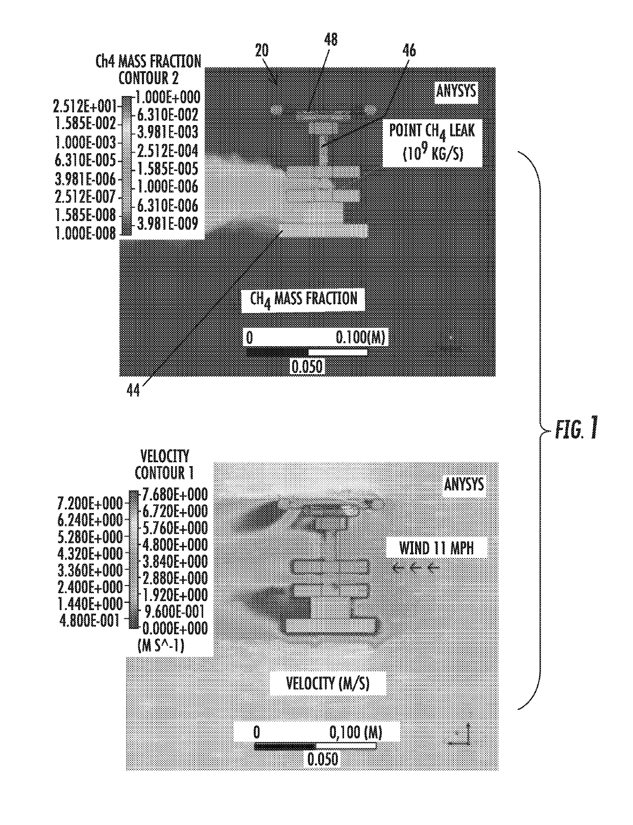
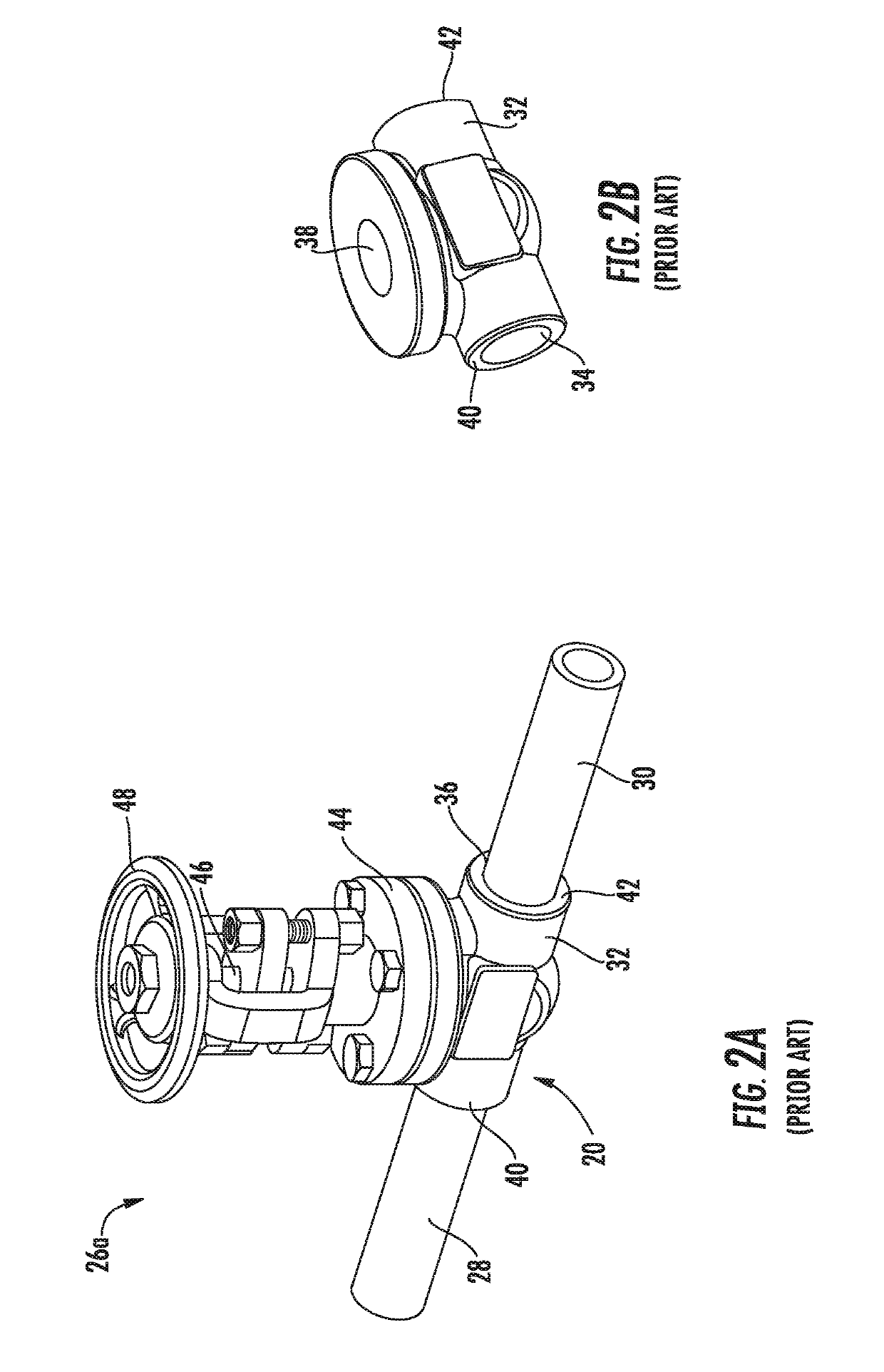
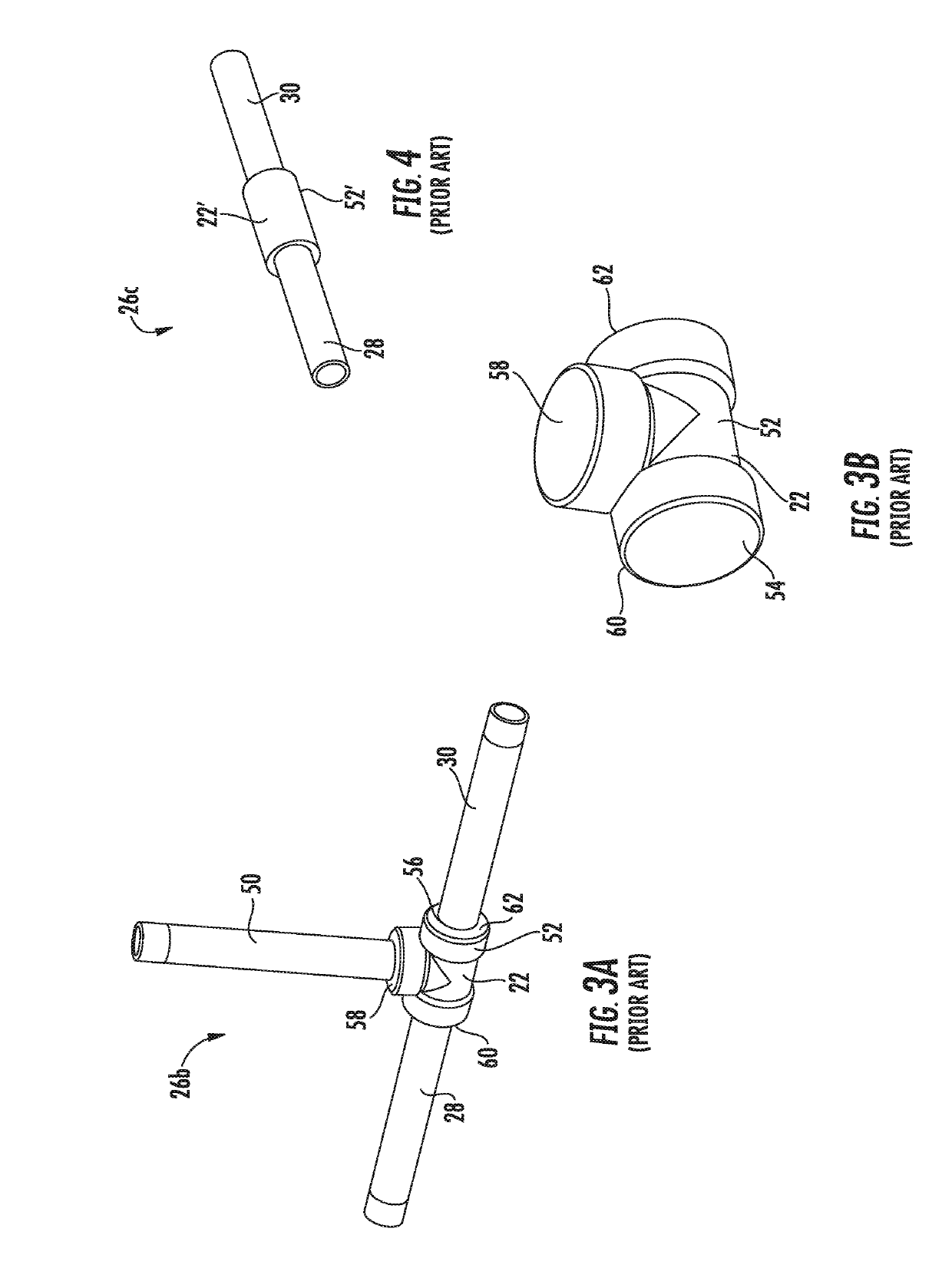
[0072]The present disclosure provides embodiments of a leak sensor assembly 100, 200, 300, 400, 500, 600, 700 which can be used to detect leaks occurring at various components of a piping system that are typically...


PUM


Abstract

The present disclosure provides a leak sensor assembly which is configured to detect the leakage of gas from a component of a piping system. The leak sensor assembly includes a housing and at least one sensor. The housing is configured to be positioned proximate to the component and forms a pocket which allows gas leaked from the component to concentrate within the pocket in a generally uniform dispersion. The at lease one sensor is configured to detect the presence and concentration of gas within the pocket of the housing.

Description

RELATED APPLICATIONS[0001]This application claims the domestic of U.S. Ser. No. 62 / 311,093, filed on Mar. 21, 2016, the contents of which are incorporated herein in its entirety.TECHNICAL FIELD[0002]This disclosure relates to the field of sensors, more specifically to the field of leak sensor assemblies and systems utilizing same.DESCRIPTION OF RELATED ART[0003]Process plants, such as petroleum refineries and chemical manufacturing facilities, have many complex issues associated with gas leaks. In October 2007, the United States Environmental Protection Agency (“EPA”) issued a document entitled “Leak Detection and Repair—A Best Practices Guide”. According to this document, the EPA has determined that leaking equipment, such as valves, pumps, and connectors, are the largest source of emissions of gases, such as volatile organic compounds (“VOCs”) and volatile hazardous air pollutants (“VHAPs”), from petroleum refineries and chemical manufacturing facilities.[0004]VOCs contribute to t...

Claims


Application Information

Patent Timeline
Patent Type & Authority Applications(United States)
IPC IPC(8): G01M3/28
CPCG01M3/28G01M3/2876G01M3/2853G01N33/0047G01M3/36
Inventor SPIEGEL, MARKOCHERNYSHOV, ALEXANDER S.PENG, WENFENGHASKELL, REICHL B.MASSNER, DAVID R.ROSCA, DUMITRU
Owner MOLEX INC
Why Eureka
Try Eureka