
Image forming apparatus

a technology of forming apparatus and cartridge, which is applied in the field of image forming apparatus, can solve the problems of complex constitution of limiting engagement between the cartridge and the apparatus main assembly, poor disassembly of the cartridge, and cartridge movement from the mounting position, etc., and achieves the effect of simple constitution and proper limiting engagemen

Active Publication Date: 2019-03-28
CANON KK
View PDF3 Cites 0 Cited by
  • Summary
  • Abstract
  • Description
  • Claims
  • Application Information

AI Technical Summary

Benefits of technology

The present invention provides an image forming apparatus that can properly engage and disengage a cartridge with the main assembly using a simple regulating member. This helps to improve the overall efficiency and reliability of the apparatus.

Problems solved by technology

Thus, in the case where the cartridge and the apparatus main assembly are engaged with each other with the mounting operation of the cartridge, when an engaging force of the engaging member is excessively strong operativity during mounting and dismounting of the cartridge becomes poor.
However, in the case where the cartridge is mountable to and dismountable from the apparatus main assembly with the light force, when package shipment such that the image forming apparatus is shipped in a state in which the cartridge is mounted in the apparatus main assembly, there is a liability that the cartridge is moved from the mounting position due to vibration, impact and the like thereof during transportation.
However, in the constitution, a plurality of component parts such as slidable members are interposed between the door and the regulating member, and therefore, a constitution for limiting an engaging state between the cartridge and the apparatus main assembly became complicated.

Method used


Image

  • Image forming apparatus
  • Image forming apparatus
  • Image forming apparatus

Examples


first embodiment

(Image Forming Apparatus)

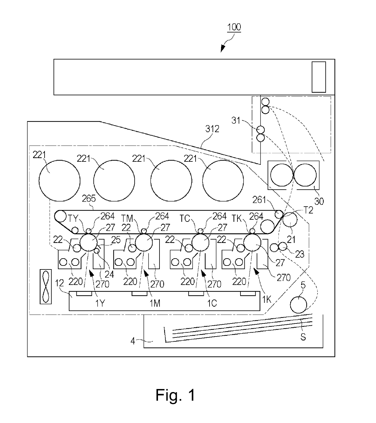
[0024]FIG. 1 is an illustration of a structure of an image forming apparatus 100. As shown in FIG. 1, the image forming apparatus 100 is an intermediary transfer type full color printer of a tandem type in which image forming portions 1Y, 1M, 1C and 1K are arranged along a surface of an intermediary transfer belt 265.

[0025]At the image forming portion 1Y, a yellow toner image is formed on a photosensitive drum 27(Y) and then is transferred at a transfer portion TY onto the intermediary transfer belt 265. At the image forming portion 1M, a magenta toner image is formed on a photosensitive drum 27(M) and then is transferred at a transfer portion TM onto the intermediary transfer belt 265. At the image forming portions 1C and 1K, cyan and black toner images are formed on photosensitive drums 27(C) and 27(K), respectively, and then are transferred at transfer portions TC and TK onto the intermediary transfer belt 265. Image forming processes for respective color...

second embodiment

[0100]Next, Second Embodiment will be described using FIGS. 12 and 13. FIG. 12 is a sectional view showing a mounted state of the drum cartridge 270 in this embodiment. FIG. 13 is a sectional view showing a state in which the drum cartridge 270 is dismountable from the image forming apparatus main assembly 100 in this embodiment.

[0101]In this embodiment, a constitution in which a locking portion 333 different in shape from the engaging portion 111 in First Embodiment is provided is employed. Further, a constitution in which a regulating member 371 different in fixing position to the small door 40 from the regulating member 271 in First Embodiment is provided is employed. Here, this embodiment has the same constitution as First Embodiment except for the constitutions of the locking portion 333 and the regulating member 371, and therefore, constituent elements in this embodiment are represented by the same reference numerals or symbols and will be omitted from description. Incidentall...


PUM


Abstract

An image forming apparatus includes a main assembly, a cartridge, a rotationally movable member, an engaging portion, and a flexible member integrally including a first supported portion, a second supported portion, and a regulating portion. A position of the regulating portion of the flexible member relative to the engaging portion is changeable by a change in a flexed state of a portion of the flexible member between the first supported portion and the second supported portion, in interrelation with a change in relative position between the first supported portion and the second supported portion with rotational movement of the rotationally movable member When the rotationally movable member is in the first position, the regulating portion is in a regulating position to limit the elastic deformation of the engaging portion.

Description

FIELD OF THE INVENTION AND RELATED ART[0001]The present invention relates an image forming apparatus, such as a copying machine, a facsimile machine or a printer, for forming an image by an electrophotographic process, an electrostatic recording process, or the like.[0002]Conventionally, in the image forming apparatus using the electrophotographic process, a process cartridge type in which a photosensitive drum and a process unit actable on the photosensitive drum are integrally assembled into a cartridge and this cartridge is mountable to and dismountable from an image forming apparatus main assembly is employed. In such a process cartridge, there is a drum cartridge in which the photosensitive drum and a cleaning member or the like are integrally assembled into a unit. Further, a developing cartridge in which a developing sleeve and an accommodating container for accommodating toner, or the like are integrally assembled into a unit, or a cartridge in which the drum cartridge and t...

Claims


Application Information

Patent Timeline
Patent Type & Authority Applications(United States)
IPC IPC(8): G03G21/18G03G21/16
CPCG03G21/181G03G21/1647G03G21/1842G03G21/1807
Inventor YASUI, RYOTA
Owner CANON KK
Learn More